

Blog | Open & Closed Loop Buck Converter | MATLAB Helper
source link: https://matlabhelper.com/blog/simulink/open-loop-closed-loop-buck-converter/
Go to the source link to view the article. You can view the picture content, updated content and better typesetting reading experience. If the link is broken, please click the button below to view the snapshot at that time.
Comparison of open loop and closed loop buck converter
August 26, 2022
By ANKIT NISHAD
Need Urgent Help?
Our experts assist in all MATLAB & Simulink fields with communication options from live sessions to offline work.
testimonials
Philippa E. / PhD Fellow
I STRONGLY recommend MATLAB Helper to EVERYONE interested in doing a successful project & research work! MATLAB Helper has completely surpassed my expectations. Just book their service and forget all your worries.
Yogesh Mangal / Graduate Trainee
MATLAB Helper provide training and internship in MATLAB. It covers many topics of MATLAB. I have received my training from MATLAB Helper with the best experience. It also provide many webinar which is helpful to learning in MATLAB.
Introduction
A Buck converter is a DC-DC step-down converter which converts the high input voltage to low output voltage by controlling the pulses. It consists of a switch which controls the connection and disconnection of load to the power supply. It draws less current from its output and is widely used in the power electronics domain. It consists of a switch and energy storing elements such as an inductor and capacitor. It can be used as a voltage regulator where the transistor is a switch. In a step-down or buck converter, when the switch is closed, the inductor allows current to flow to the load. When the switch is opened, the inductor supplies the stored energy to the load and the continuous output current gives less output voltage ripples.
Circuit Configuration
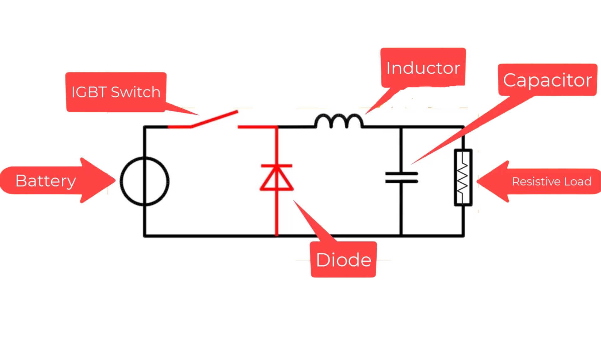
The circuit comprises a battery that provides input voltage, a switch for controlling output voltage, two energy storing elements inductor and capacitor for its main circuitry process and a load across which output voltage is measured. It has two states, on and off states. In the on-state, the inductor stores the energy and in the off-state, the capacitor stores and supplies energy where then only a calculated portion of the supply voltage and current is allowed for the load, instead of the relatively bigger peak voltage input source. This is a brief of the process of the buck converter.
Controlling Measures of Buck Converter
In the power electronics domain or even in real life, controlling aspects are one of the most important aspects always. Things need to be controlled for the safe working of our life or even the circuits before, which might cause some other side effects that might not be good. Here, the value of the output is controlled according to our needs or the controlled voltage value we need across the load for its proper working. There are two types of control measures, i.e., open loop-controlled system and closed loop-controlled system. These two controlling measures will be used in the modelling of the DC-DC buck converter, and the best controlling measure will be found for this circuit.
Open loop Controlled DC-DC Buck Converter modelling
What is an Open loop controlling system?
An open loop-controlled system is a control loop system where a group of elements are connected in a sequence to perform a specified function (or task) where the output is controlled without using any feedback and has no influence or effect on the control action of the input signal. There is no chance to correct the transition errors in open loop systems, or there is more chance to occur errors. But still, these controlling systems are widely used in many domains because of the input being free of the output values.
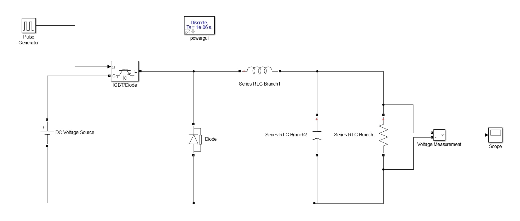
Modelling of Open-loop Buck converter in MATLAB Simulink
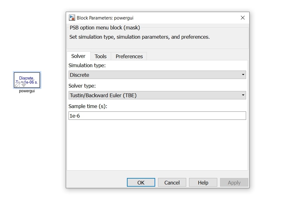
The open loop model of buck converter should be made under some considerations where it will be a discrete mode of sample time  (written in Simulink as 1e-5) which makes the model look the same as a buck converter would work in reality.
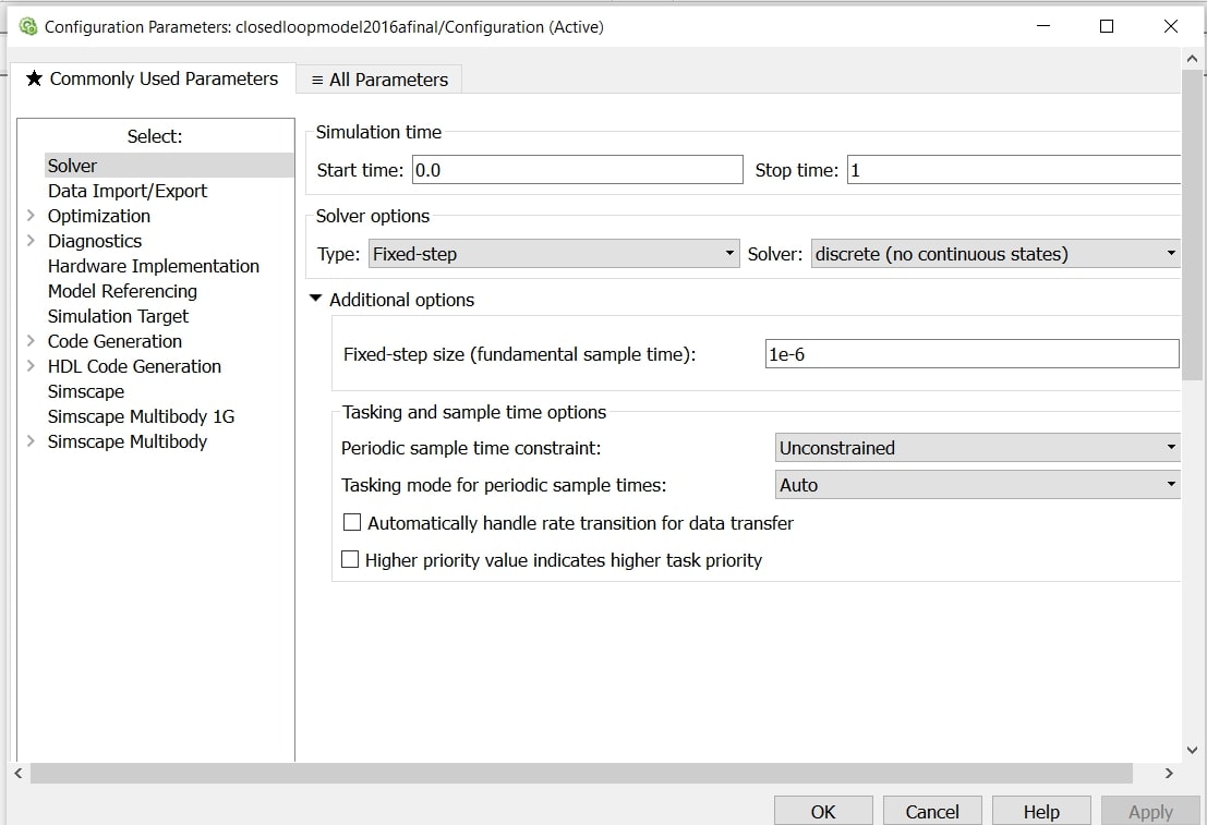
Setups before modelling-
Select a new model in Simulink and follow the mentioned below,
- A powergui block is taken from the library browser and select the simulation type discrete and sample time 1e-5.
The theory behind selecting the parameters of components: -
There are numerous buck converters made in power electronics of different ratings. Every Converter has a different combination of values of inductor and capacitor according to the ratings required in a particular circuit. Here in this model, a certain combination of inductor and capacitor is taken for which the voltage output is uniform and has fewer ripples. You can also choose a combination of inductor and capacitor for which the voltage output has fewer ripples and is uniform.
The formula of the Buck converter
The output voltage of the buck converter is the input voltage times the duty cycle.

Duty Cycle (D)
The duty cycle is the ratio of the signal on time to its total time period.

In this model, D is taken 0.6 and the RLC branch where, 
 farad and R = 1 ohm and input voltage
  Volts
Volts
Modelling: -
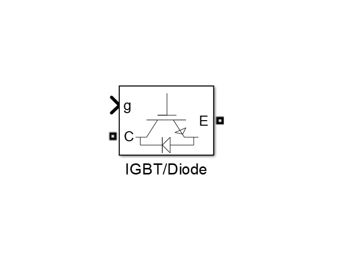
- Search the following components in the library and select them for the blank model.
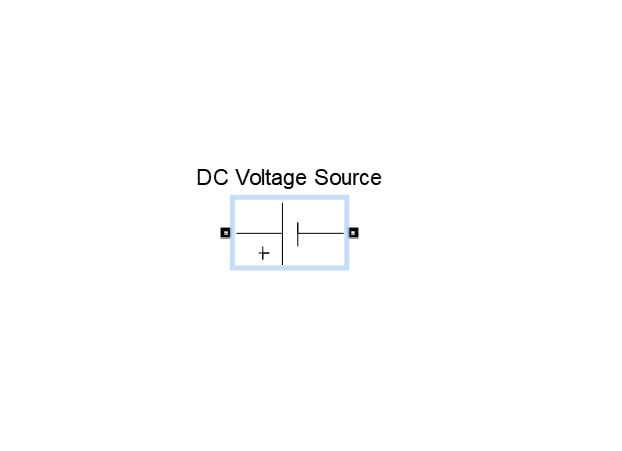
Take DC Voltage Source 100Volts
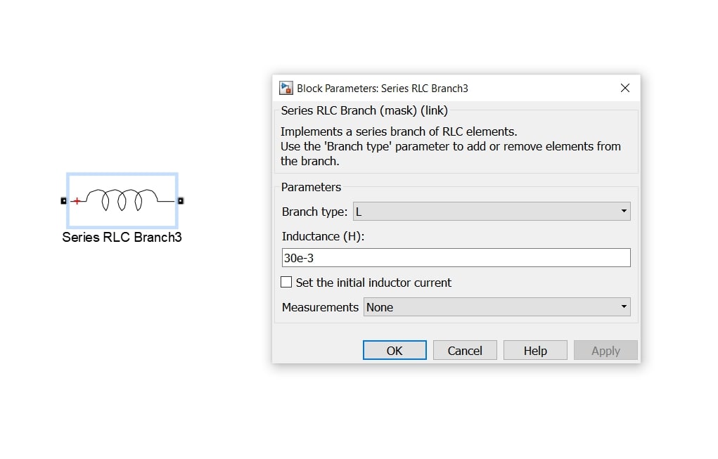
Type the inductance 30e-3 i.e.,  henry
henry
Type the inductance 30e-3 i.e., henry
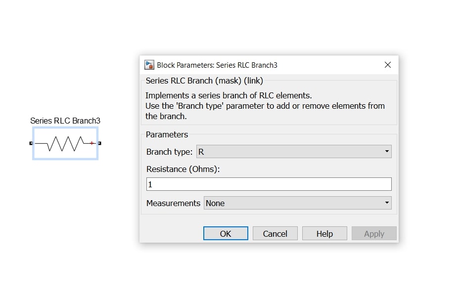
Type Resistance 1 ohm
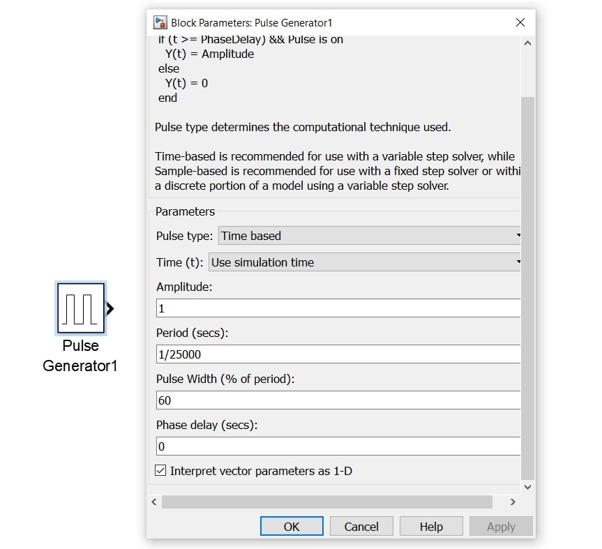
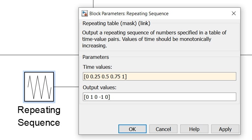
Take the period  and pulse width 60 i.e., D=0.6
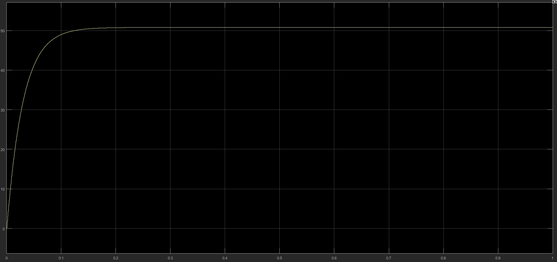
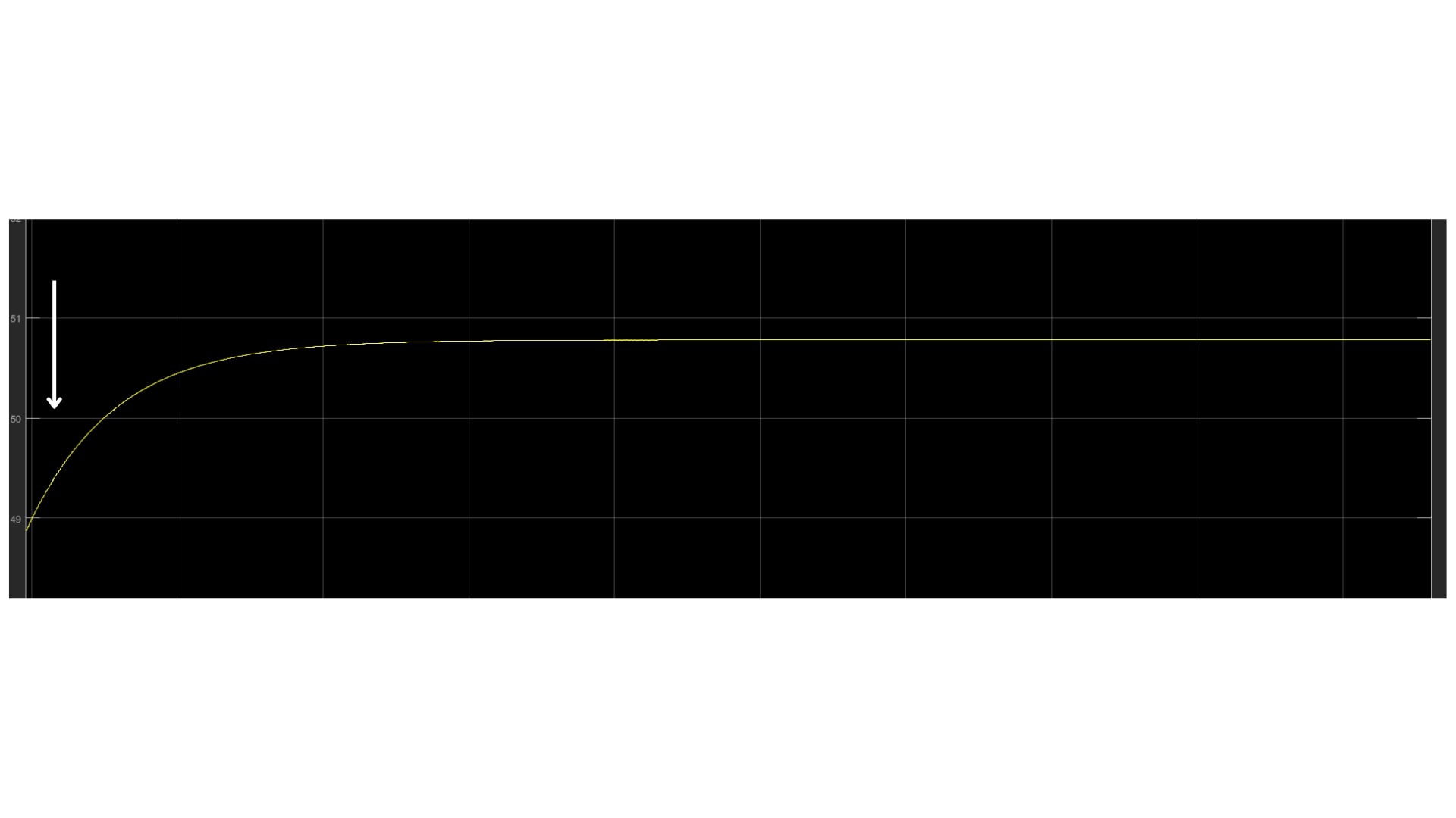
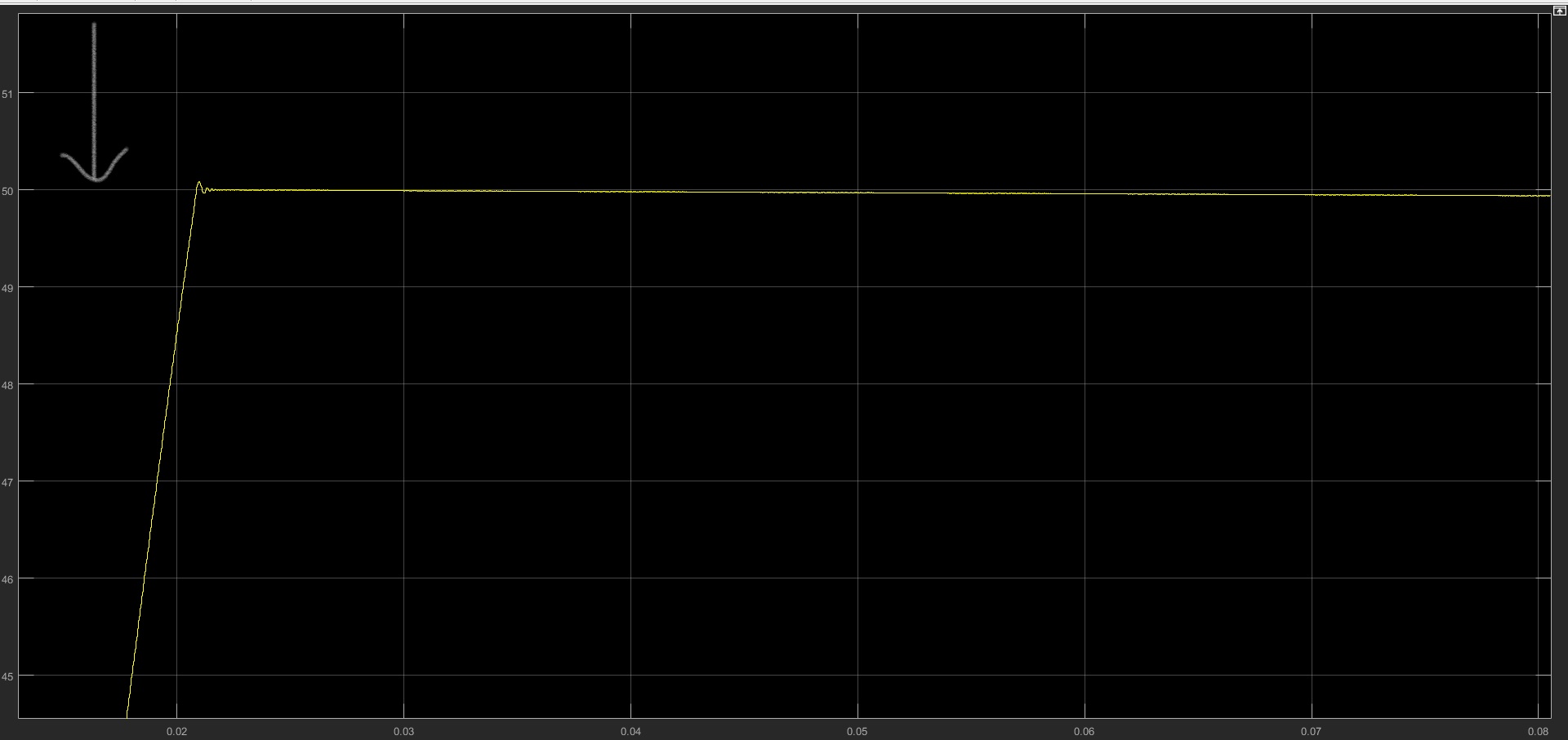
- This is the output of an open loop controlled buck converter which, after setting reference voltage, doesn't give voltage perfectly 50, and in the power electronics domain, even a minor fluctuation of voltage is very sensitive to the circuits.
- Let's check out if the closed-loop Converter gives any different results.
Get Access to
Models & Report!
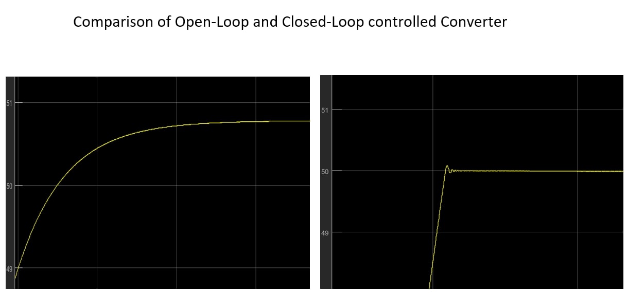
In an open loop buck converter, there is no feedback from output to input, contrary to the closed loop, which has a feedback circuit. Study the comparison of two models with simulation; Developed in MATLAB R2021a with Simulink, Simscape and Simscape Electrical Libraries.
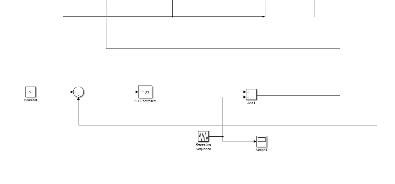
Closed loop Controlled DC-DC Buck Converter modelling
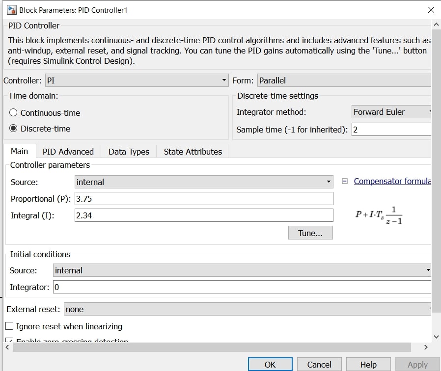
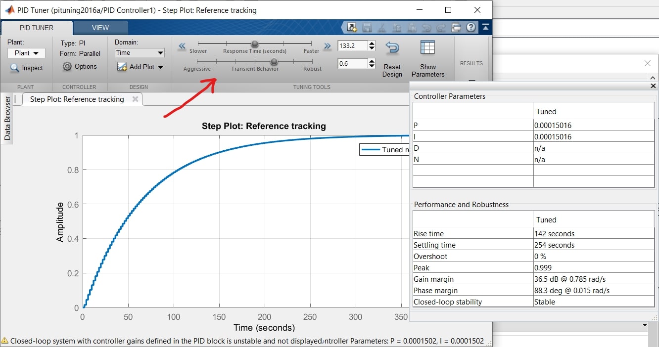
In the closed loop converter, the IGBT switch is controlled by the pulses generated from the feedback of the output, which is compared with the input and the error or difference is compensated by controllers called PID (Proportional Integral Derivative). Usually, PID is used for very complex circuits; in this model, we will use PI (Proportional Integral) to get a good output.
What is PID Controller?
PID controller is a controller used in a closed loop feedback system where it takes feedback from the output and compares it with the input, and then compensates or aims to reduce the difference to zero through its proportional, integral and derivative algorithms. Let's see the three terms' characteristics.
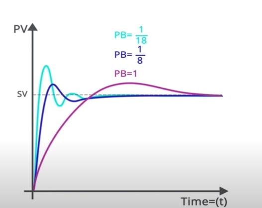
Proportional: -
- This is the parameter that determines how fast the system responds, for controller term 'Gain' used for proportional.
- The more the P value, the fast the system will respond and the more sensitive and less stable it will become.
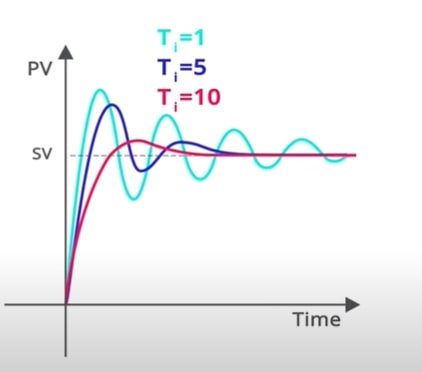
Integral: -
- The parameter determines how fast, steady-state error is removed.

 is measured in repeats/second, seconds/repeat, repeats/min and mins/repeat
- Smaller minutes per repeat will create larger integral actions, or larger values in repeats per minute measurement will create larger action.
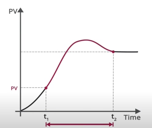
Derivative: -
- The derivative constant is for predicting change, or the rate of change measured in the process variable or how far in the future you want to predict the rate of change.
- It is the rate of change in the process variable, and the process variable must be a very clean signal; hence no noise within the signal; that's why the derivative is not often used.
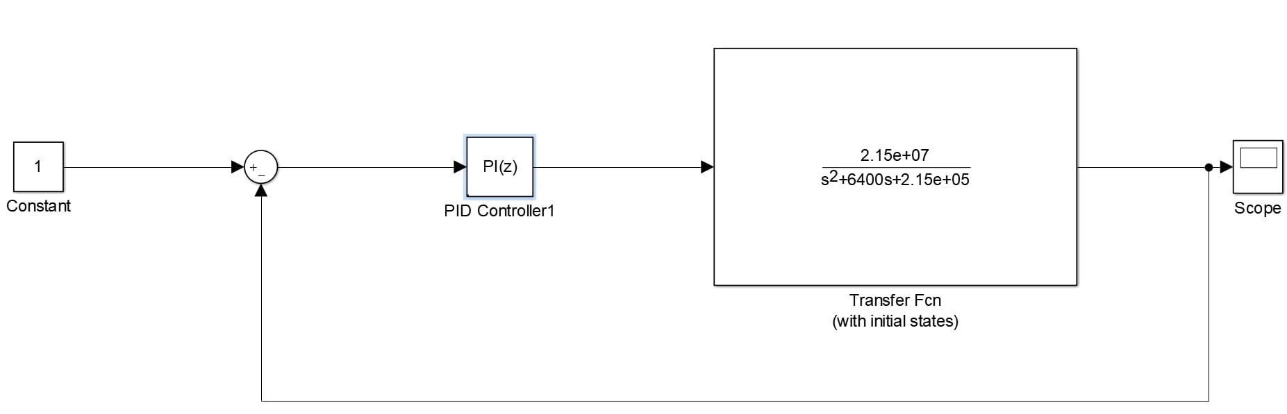
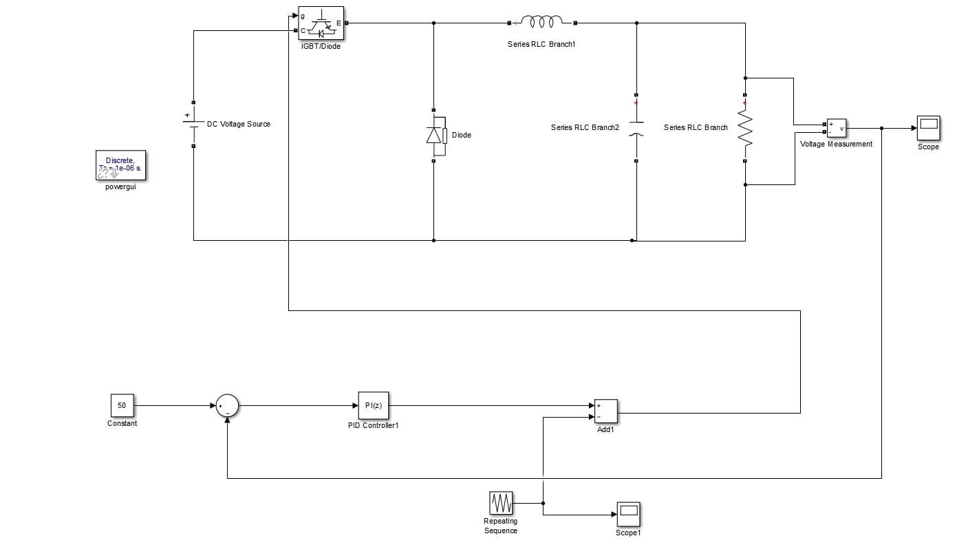
Modelling of Closed loop Buck converter in MATLAB Simulink
The theory behind selecting the parameters of components: -
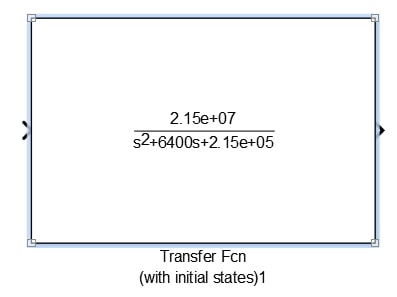
To tune a model through PI, we need to get the transfer function of the model to be tuned. The transfer function of the buck converter is,

After putting the values of L, C and R same as taken in the open loop model, the transfer function looks something like this,

Modelling: -
Take a transfer function with initial states and put the values the same as calculated.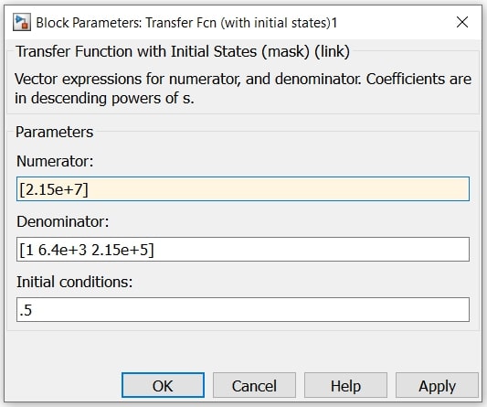
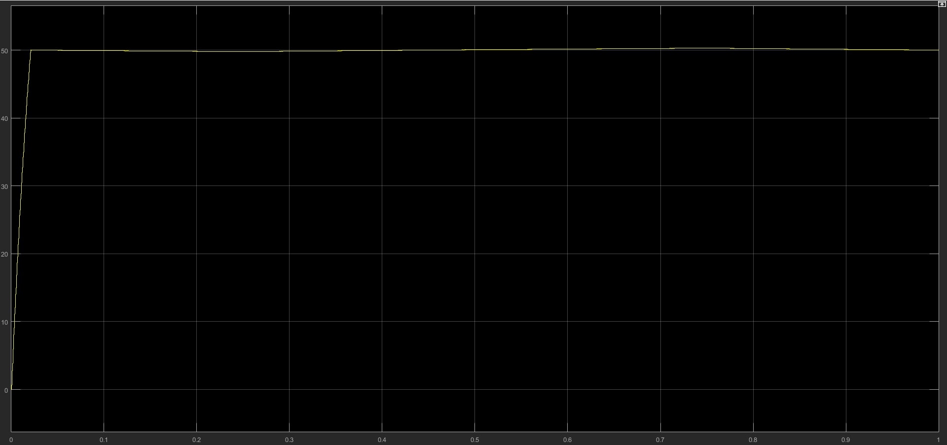
Conclusion
Comparing the output of the open loop buck converter and closed-loop converter, the closed-loop Converter gives a good output with precise results because of its feedback system.
Did you find some helpful content from our video or article and now looking for its code, model, or application? You can purchase the specific Title, if available, and instantly get the download link.
Thank you for reading this blog. Do share this blog if you found it helpful. If you have any queries, post them in the comments or contact us by emailing your questions to [email protected]. Follow us on LinkedIn Facebook, and Subscribe to our YouTube Channel. If you find any bug or error on this or any other page on our website, please inform us & we will correct it.
If you are looking for free help, you can post your comment below & wait for any community member to respond, which is not guaranteed. You can book Expert Help, a paid service, and get assistance in your requirement. If your timeline allows, we recommend you book the Research Assistance plan. If you want to get trained in MATLAB or Simulink, you may join one of our training modules.
If you are ready for the paid service, share your requirement with necessary attachments & inform us about any Service preference along with the timeline. Once evaluated, we will revert to you with more details and the next suggested step.
Education is our future. MATLAB is our feature. Happy MATLABing!
About the author
ANKIT NISHAD
I am working as a MATLAB Developer Intern at MATLAB Helpers.
Recommend
About Joyk
Aggregate valuable and interesting links.
Joyk means Joy of geeK