

Ethernet For Hackers: The Very Basics
source link: https://hackaday.com/2024/02/12/ethernet-for-hackers-the-very-basics/
Go to the source link to view the article. You can view the picture content, updated content and better typesetting reading experience. If the link is broken, please click the button below to view the snapshot at that time.

Ethernet For Hackers: The Very Basics

Ethernet is ubiquitous, fast, and simple. You only need two diffpairs (four wires) to establish a 100Mbit link, the hardware is everywhere, you can do Ethernet over long distances easily, and tons of the microcontrollers and SoCs support it, too. Overall, it’s a technology you will be glad to know about, and there’s hundreds of scenarios where you could use it.
If you need to establish a high-bandwidth connection between two Linux boards in your project, or maybe a Linux board and a powerful MCU, maybe make a network between microcontrollers, Ethernet’s your friend. It also scales wonderfully – there’s so much tech around Ethernet, that finding cables, connectors or ICs tends to be dead easy. Plus, the world of Ethernet is huge beyond belief. Ethernet as most of us know it is actually just the consumer-facing versions of Ethernet, and there’s a quite a few fascinating industrial and automotive Ethernet standards that flip many of our Ethernet assumptions upside down.
Now, you might be missing out on some benefits of Ethernet, or perhaps misunderstanding how Ethernet works at all. What does it mean when a microcontroller datasheet says “has Ethernet interface”? If you see five pins on an SBC and the manufacturer refers to them as “Ethernet”, what do you even do with them? Why does the Raspberry Pi 4 SoC support Ethernet but still requires an extra chip, and what even is GMII?
Transmit The Basics
Ethernet is fundamentally about point to point connections – a single cable connecting two devices. If you have multiple devices you want to tie together into a network and Ethernet is what you’ve got available, you’ll want to use a switch, or a router with a builtin switch, or something else that has multiple Ethernet ports, then do individual point-to-point links between the switch and your devices, forming a star topology network. It used to be that you could use a coaxial cables for Ethernet and wire a single cable between computers, but those days are long gone, and the speeds were low enough that the major reason to miss those times is nostalgia.
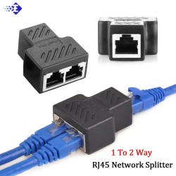
Ethernet ports and cables, demonstrated by cursed-looking but pretty useful adapter
There’s two versions of Ethernet you will encounter nowadays when it comes to speed – 100 Mbps (Mbit/s), often known as 10/100 because it usually also supports the old 10 Mbps mode, and 1 Gbps, known as Gigabit Ethernet. There’s also 2.5 Gbps, slowly becoming more commonplace in higher-end consumer tech like laptops, PCs and routers, but it’s yet to grace microcontrollers and SBCs, and I wouldn’t hold my breath – 100 Mbit/s is still enough for a ton of things. 5 Gbps and 10 Gbps are apparently on the horizon, but don’t expect to link up at that speed yet, unless you reuse some server card , invest some good money into it, or take time figuring out a cheap way. Of course, that’s bits per second, not bytes – if you want to calculate maximum file transmission speed where bytes/second is commonly used, you want to divide by 8, and subtract about 5% for packet overhead.
Physically, Ethernet tends to use cabling known as CAT5e, and connectors known as RJ45, with the proper name technically being 8P8C. Both the cables and the connectors are super commonly available, no end of life in sight. So, if you want to connect two boards together in a project of yours, maybe even with a shielded cable, using Ethernet cabling is a good bet – even if your project has no trace of Ethernet to be seen.
Speaking of cabling, Ethernet cables most certainly deserve their own part of the article. Let’s talk about cabling in as much detail as could be useful for an average hacker.
All The Wires
An Ethernet CAT5 cable has four twisted pairs inside of it, each one used for a separate differential pair – so, eight wires on total. Higher-speed versions of Ethernet like 2.5 Gbps will often wants higher-grade cabling than CAT5 – CAT6 or even CAT7, manufactured to a higher standard, but CAT5 (or CAT5E specifically) is what you’ll see the most of. Internally, some cables use multi-strand wires and some use solid core wires, and they work best in different scenarios. Short patch cables (known as “patchcords”) are better with stranded wiring, because it’s more flexible and easier to handle. However, stranded cables are less durable, and don’t work as well at longer distances. For more permanent and longer cabling, people tend to use solid core wiring, as it’s generally higher-quality, which helps on longer cable runs. Also, there’s different types of outer insulation – some are more fireproof, some are less toxic, and some are more resistant to environmental influence like UV light.
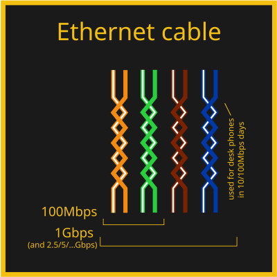
Out of the four pairs, 100 Mbps Ethernet only actually uses two of them, but 1 Gbps Ethernet uses all four. That’s why, on cheap old Ethernet hardware like low-end home routers with 100 Mbps ports, it’s not uncommon to see Ethernet sockets with only four pins out of eight – saving money by all means possible, after all, the two pairs in the cable would not be used anyway. There’s also hack potential in this, for instance, you can pull two 100 Mbps Ethernet links through a single CAT5 cable – that’s how my own Internet uplink used to work for a while about a decade ago, and that’s what the adapter pictured above does. And you can pull power through those pins in parallel with the Ethernet uplink, we’ll talk about that later, too!
Some Ethernet cables have internal shielding, but hardly anyone requires it – it’s used more in industrial or sensitive environments, and it might be required for higher-speed Ethernet standards too, but it’s rarely ever seen at home. So, most cables are not shielded, and they’re referred to as UTP (Unshielded Twisted Pair). There’s quite a few types of shielded Ethernet, which you might see referred to as FTP, SFTP, S/UTP or such – S- types (Shielded) wrap individual pairs or the cable in copper braid, FTP (Foiled) wraps them with foil, SFTP does both, there’s three-four different acronyms for each type of shielding combination, but don’t worry, you are not expected to remember this, just refer here or here if you ever need to know more. Also, don’t confuse it with SFP, that’s different! The type of shielding is typically written on the outer insulation along the length of the cable, too. If you are looking at a bundle of Ethernet cables of all kinds and you just want to find a shielded Ethernet cable for whatever reason, say, your robot’s internals, good shorthand is looking at the connector – it’s going to be metal-plated. Oh, and if you want the shield to be effective, at least one end has to actually be connecting that shield to something – many cheap devices don’t bother and use connectors fully made of plastic, with no plug shield connections in sight.
There’s only one standardized Ethernet connector, but there are a few different ways to cook it! In particular, you should know a few things about the standard pair-to-pin mappings, and how to actually terminate the cable in an Ethernet plug.
Plugs, Crimps And Mappings
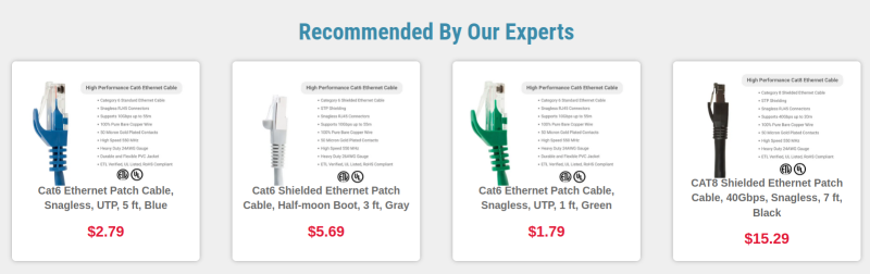
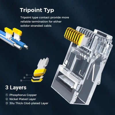
The usual Ethernet connectors are RJ45, technically correctly referred to as 8P8C. The plugs are easy to find in a wide variety of places, though with both CAT5e cabling and connectors, you don’t want to go for the cheapest options possible, especially given how much cabling claims to be a higher category than it actually is. With cheap plugs, they’ll be more likely to produce a faulty connection, or have the locking tab break away easily – fixable either through recrimping, strategic application of cable ties, or by using one of the ubiquitous plug sleeves.
The locking tabs are brittle enough, that all the fancy cables include some sort of tab protection
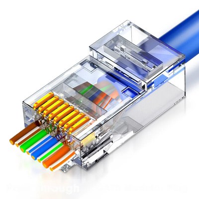
Most consumer-oriented Ethernet cables come with plug connectors put on them, but you can easily build your own Ethernet cables out of unterminated CAT5e lengths and plug connectors, as long as you can crimp the plugs onto the cable. There’s even Ethernet plugs that make the crimping process easier for beginners by letting you cut the wires after you insert them through, instead of painstakingly cutting them to exact same length before insertion! If you’re looking to learn how to crimp Ethernet cables, a YouTube tutorial is perhaps the best, and there’s no shortage of blog posts with pictures either – crimping is a craft extensively covered online. There’s one thing that you will inevitably need, and that’s a crimping tool.
A crimping tool is a handheld jig that compresses the plug pins in a way that makes the individual plug pin blades cut through the wire insulations and make electrical contact, which requires pressure applied very tactically and from a correct angle. You can also try and crimp a plug with household tools, but you’ll thank yourself for not doing that. Remember, having a proper crimping tool will save you both time and money, as well as a heap of frustration, because debugging Ethernet cables that make intermittent contact is not pleasant in the slightest. The most cheap crimping tools aren’t great to use and can lead to faulty crimp, so if you are about to do some crimping and got money to invest into proper tools, you will want to get a crimping tool that has great third-party reviews. Alternatively, see if your friendly neighbourhood hackerspace or networks engineer has a crimping tool you can borrow! If you need to test your crimping results, cable testers are cheap, and we’ve covered quite a few DIY ones.
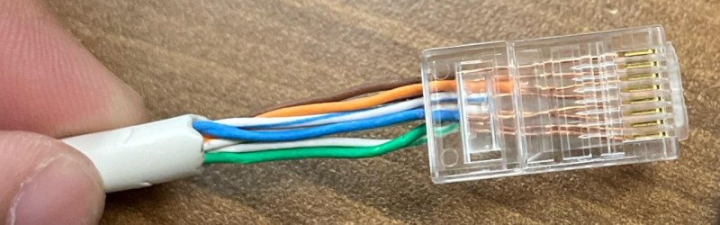
Not a good crimp.
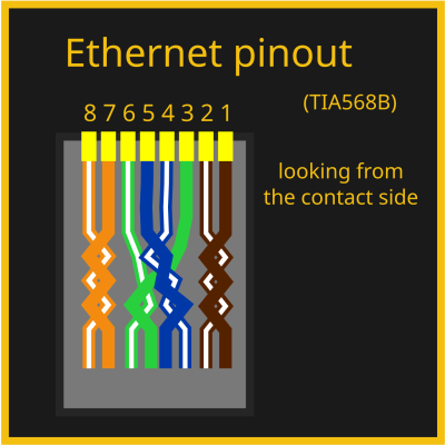
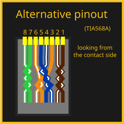
Of course, there are eight wires and eight pins, so you might be wondering – is there a mapping? The good news is – there is indeed! The bad news is – there are two of them. Fortunately, it’s easy to choose – the T568B mapping is the most commonly one used, with the T568A mapping being way less popular. Wikipedia tries to convince you that T568A is technically the best mapping ever, but you shouldn’t listen to it – a random cable in your cable box is way more likely to use T568B than T568A, and same goes for Ethernet cables worldwide.
You won’t need to learn the mapping, but if you want to, it will be all that easier as soon as you notice that the color and white wire pairs alternate. One quirk – the blue pair is in the connector center, which might feel counterintuitive. Here’s a fun fact, though – back in two-pair-utilizing 10/100Mbps days, this pair would sometimes be repurposed in offices, to carry a desk phone line alongside an Ethernet link to a worker’s desk within a single cable. You have to use the same mapping on both sides of the cable. However, in earlier days, there were cables where you had to use both mappings at different ends. Let’s take a small detour and learn about these cables, that you might just encounter if you work on really old tech.
Crossover
You might have heard of a thing called crossover cables. These were 10/100 MBps era Ethernet cables where the ends were crimped in two different ways, one in A variant and one in B variant – essentially, crossing RX and TX pairs. Direct (same pinout on both ends) mapping cables were used for switch-to-PC connections, and crossover cables could be used to connect two PCs or switches directly. Reason is, at the time, Ethernet expected you to cross RX and TX pairs ala UART, but ports on devices like switches would have them already crossed for convenience. Of course, this created a fair bit of problems at the time whenever you needed to rewire things.
However, for almost two decades now, crossover cables have been unnecessary, because every self-respecting Ethernet interface has adopted the technology called Auto-MDI-X – it lets you use both crossover and straight cables for connecting anything to anything, automatically detecting RX and TX and adjusting accordingly. You don’t need to bother with crossover cables nowadays, they have never been a thing for Gigabit Ethernet, and you’ll rarely ever find a piece of tech that doesn’t support Auto-MDI-X. If you want to learn more about crossover cables and tons of other Ethernet stuff, read here. It’s a still good thing to know exists in case you’re working with something seriously old that’s Ethernet-equipped, or if you stumble upon “crossover cable” as a term somewhere and wonder if you have a knowledge gap.
So Much More To Learn
We’ve covered pinouts, cabling and connectors, and that alone makes for a solid understanding of how Ethernet works at its core, at least as far as consumer tech is concerned. This is the surface-level of Ethernet, that you want to keep in mind as you hack on it further, and if you’ve had any knowledge gaps, hopefully this article has helped you cement your understanding. If you want to learn more in-depth, I’ve linked a couple articles inline – there’s never a shortage of Ethernet reading material online! Now, a lot of it is outdated or wrong, but the pages I’ve linked here, look pretty alright. Also, here on Hackaday, [Maya Posch] has written about Ethernet before in more depth – check her articles out!
There are so many more sides to Ethernet, however – physical level insights, microcontroller and SBC requirements, MII and GMII, MACs and PHYs, magnetics and magjacks, mediaconverters, Power over Ethernet, switch ICs, embedded Ethernet, and a good few more hacker bits and pieces. Next week, with the base knowledge in hand, we shall dive further!
Featured image: “10base-T” by [gratuit]
Recommend
About Joyk
Aggregate valuable and interesting links.
Joyk means Joy of geeK