

Tempus Nectit Knitting Clock
source link: http://kylerank.in/tempus_nectit/
Go to the source link to view the article. You can view the picture content, updated content and better typesetting reading experience. If the link is broken, please click the button below to view the snapshot at that time.

Design
The design is split into a few logical components:
- Electronics (stepper motor controls)
- Software (rotating the stepper a pre-defined amount according to a schedule)
- Knitting Machine (preparing an off-the-shelf knitting machine for this project)
- Case (building some sort of case to house it)
Electronics
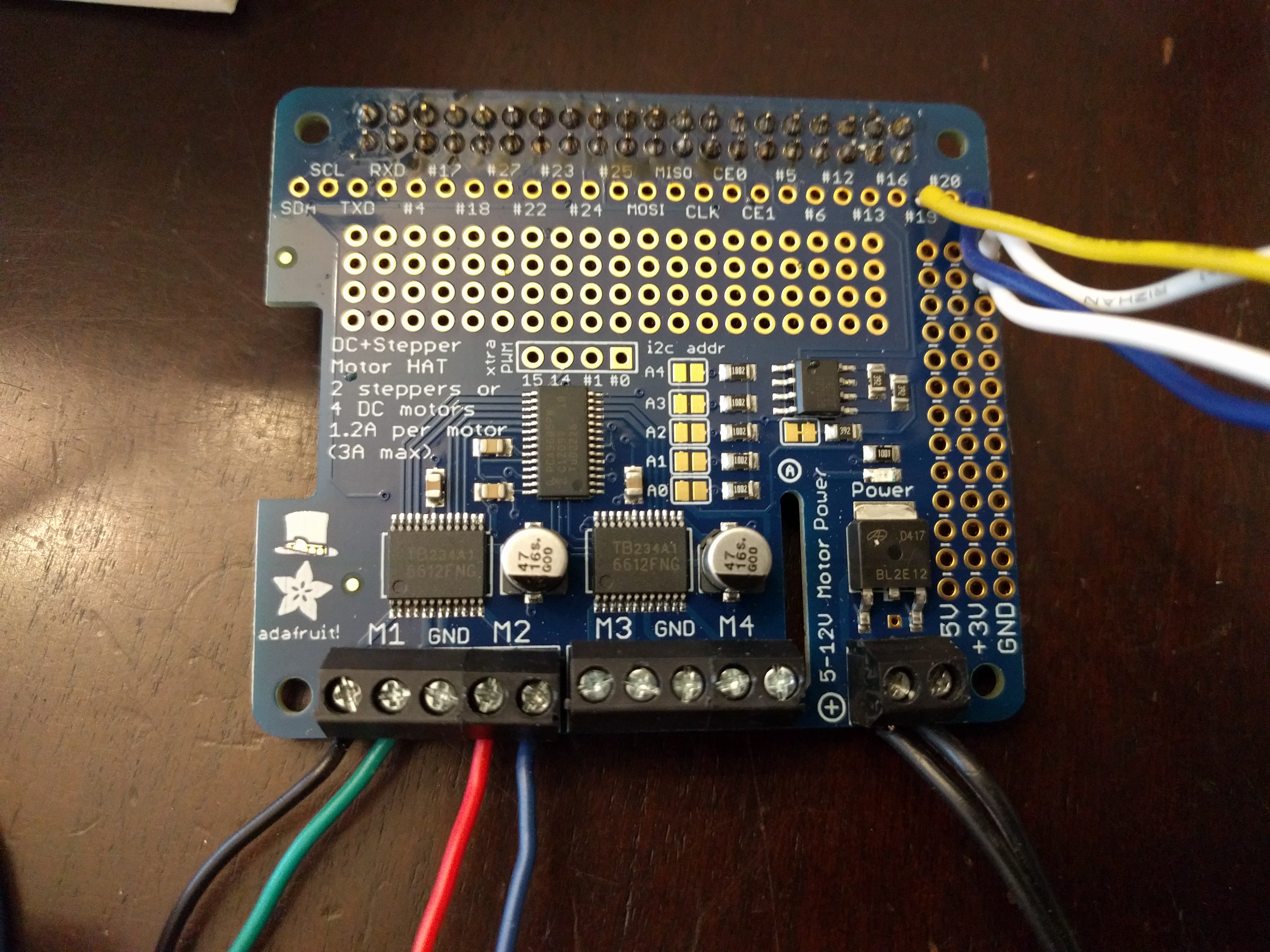
One of the first parts of the design I worked on was the Adafruit motor hat for a Raspberry Pi. The kit is pretty straightforward and I essentially just followed the their motor hat documentation to assemble and test the motor hat with my Raspberry Pi. I ended up attaching a small stepper motor that was part of an out-of-commission 3D printer I had lying around.
The motor hat requires its own power supply that ranges between 5 and 12 volts. Like many geeks, I have a box in my garage that contains old power bricks, so I fished through there for some options. Something I learned from 3D printing was that stepper motors have more torque with more voltage, but I also knew that it also makes the motors louder. I tried both a 9 and 12 volt power supply and ultimately decided to go with the 9 volt, 1 amp power supply for this project as it took up a bit less space and it seemed to provide plenty of power for the stepper.
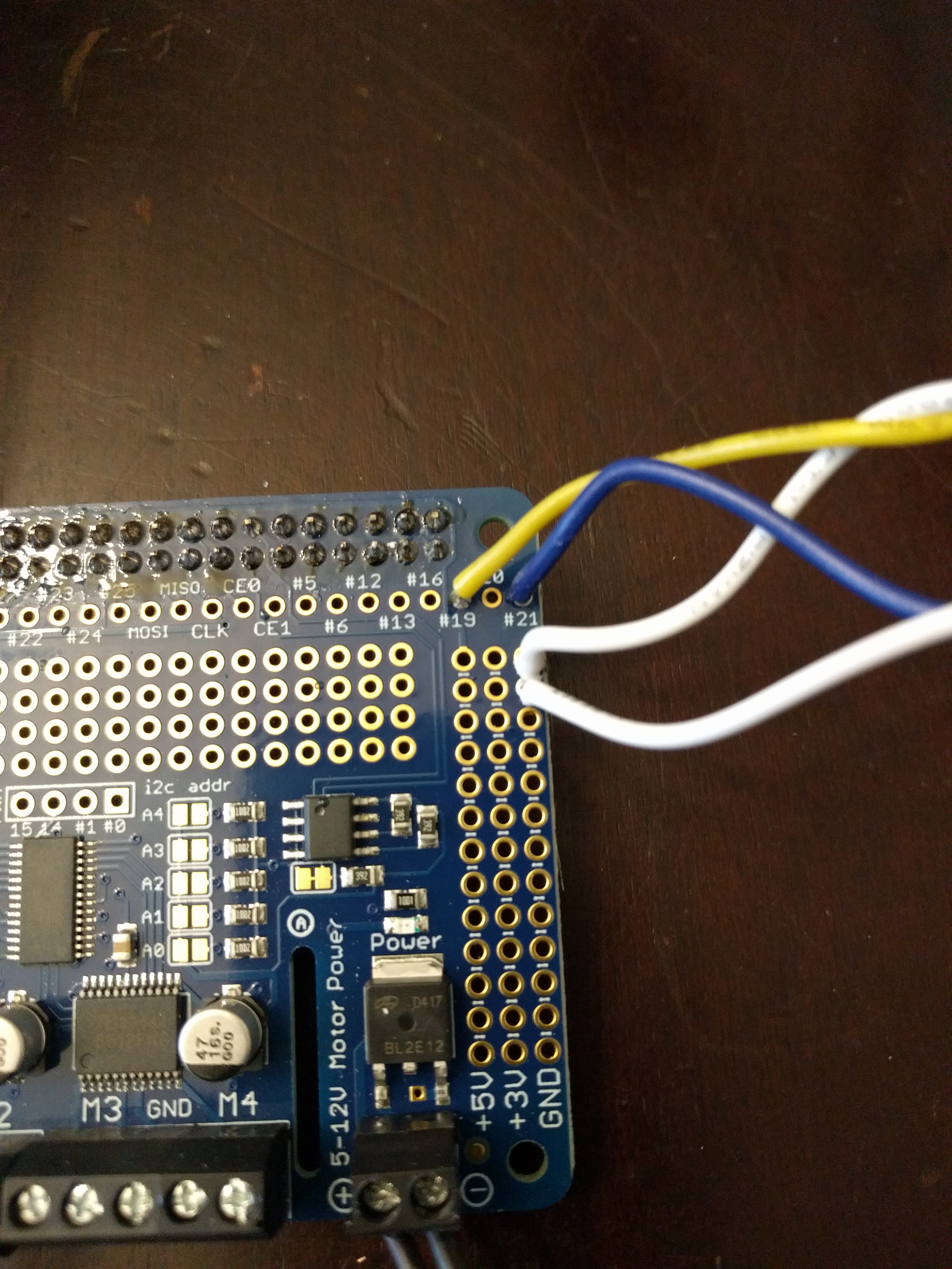
Early in the project I realized that it would be useful to be able to control the stepper motor manually with push buttons, instead of having to SSH into the machine and run scripts. I recalled in a past Adafruit project to turn a Pi Zero into a small game system, that you could attach small electronic buttons to GPIO pins on the Raspberry Pi.
I dug through some electronics kits I had around (badges from conferences) and found a few push buttons I could use. Then I looked up which GPIO pins I should use for the purpose and where they mapped on the Adafruit motor hat and followed Adafruit's guide on GPIO buttons to attach the buttons to GPIO pins 19 and 21 and corresponding ground pins using some 22AWG solid core wire. Their guide also provided some sample python code I could use to register button events and then trigger motor movements. I soldered the wire to one side of the buttons and ended up removing the pins from the other side for ease of installation later.
I decided on two buttons so that I could move the motor one stitch in either direction. This turned out to be particularly useful when casting on, as you need to rotate the knitting machine a full 360 degrees, slowly, while winding yarn under odd-numbered hooks and around even-numbered hooks. Normally you do this with one hand while the other is cranking the hand-crank on the knitting machine, and while I initially thought I'd write a script just for casting on, it turned out having this manual control that moved one stitch at a time was far more convenient.
Software
The Raspberry Pi is running standard Raspbian as its OS so that it matched the platform in the Adafruit examples. This made it easy to go from a blank OS to one that was able to run stepper motor and GPIO examples from Adafruit.
I needed to write custom software so that I could control the knitting machine with precise steps. All of the main examples from Adafruit were in Python, but I only have a passing familiarity with the language, as my software development experience has traditionally been in C, Perl, and Bash. Fortunately, Python syntax is similar enough to the languages I know, and the examples are clear and simple, so I used Python for the whole project.
The sample scripts on Adafruit worked to cause my stepper motor to rotate each direction, but what was more important for the next step in the project was to demonstrate that I could actually control the knitting machine itself. I found a motor adapter on Thingiverse for the 48 hook Sentro knitting machine and modified it slightly in Tinkercad so I could attach it to my stepper motor.
This stepper motor originally attached to a shaft on the 3D printer using a short length of aquarium tubing and some 3D-printed clamps. I stuck with that idea and resized the hole in the motor adapter so that I could just shove the motor and tubing in there. After a little trial and error, I figured out the number of steps to move the knitting machine one stitch and ended up writing a few simple scripts that would advance the knitting machine in different ways. For instance here is my test script that advances a single stitch:
#!/usr/bin/python

import time
import board
from adafruit_motorkit import MotorKit
from adafruit_motor import stepper

kit = MotorKit(i2c=board.I2C())

for i in range(54):
#    kit.stepper1.onestep(style=stepper.SINGLE,direction=stepper.BACKWARD)
    kit.stepper1.onestep(style=stepper.DOUBLE)
#    time.sleep(.01)

#for i in range(864):
#    kit.stepper1.onestep(style=stepper.MICROSTEP,direction=stepper.BACKWARD)
#    kit.stepper1.onestep(style=stepper.MICROSTEP,direction=stepper.FORWARD)

kit.stepper1.release()
Note all of the commented out sections. I experimented (and continue to experiment) with the different types of steps you can perform. The biggest challenge I found was trying to decide between the added stepper strength of double steps, or the more precise and quieter, but weaker microsteps. Also note that it takes a lot more microsteps to equal a single or double step.
Another aspect I experimented with was the amount of time to sleep between single or double steps. While microsteps didn't need a sleep function, without any sleeps during single or double steps the motor goes full speed and creates a violent and loud reaction when it cranks the knitting machine. This is useful when you want to trigger a full and fast rotation to simulate a full day of knitting, but is too much for normal operation. This is still an area I'm tinkering with in the final script.
Ultimately I found that the smaller stepper motor from my 3D printer was alternatively jamming and slipping inside of the aquarium tube more than I'd like. I ended up ordering a more powerful replacement stepper motor that had a flattened section on the motor shaft and created a new gear adapter to fit it, and that seemed to resolve most of the issues.
Knitting Machine Daemon
There was a point where I considered writing a script that would advance the machine one stitch, and then run that script hourly using cron. However, once I added button control to the design, it was clear I needed to manage the buttons at the very least with a daemon that started at boot, and ultimately decided to manage all functions within the same daemon.
This script is a work in progress, but is stored at /usr/local/bin/knitting_clock_daemon.py. It runs in an infinite loop. First it checks the time and if it finds itself at the top of the hour, it will move the stepper forward. It divides the number of steps into segments so it can "chime" the hour, with a short sleep in between. Once it is finished moving, the script will sleep for 61 seconds to avoid the risk of triggering twice in an hour.
If you read the script you will see that I also have the motor move backwards first before moving forward. This is to attempt to prevent binding, which these cheap plastic machines sometimes want to do since there is a lack of precision in how they are machined. Moving backward briefly, and quickly, tends to reduce the risk of binding in my experience.
If it isn't the top of the hour, the script detects button presses from either of the two buttons and steps either forward or backward one stitch. It sleeps a small amount between each invocation of the loop so the CPU isn't busy, but you can still hold down one of the buttons and have it advance as you would expect.
Along with this script I created a simple systemd unit file at /etc/systemd/system/knitting_clock_daemon.service to run it at each boot:
[Unit]
Description=Start Knit Machine Controller Daemon
Requires=basic.target
After=basic.target rescue.service rescue.target

[Service]
Type=simple
ExecStart=/usr/local/bin/knitting_clock_daemon.py
Restart=on-failure

[Install]
WantedBy=multi-user.target
Once the unit file was in place, I ran sudo systemctl daemon-reload; sudo systemctl enable knitting_clock_daemon to enable it at reboot.
Deciding Daily Stitches
Ultimately as I switched from a 48-hook to 22-hook knitting machine (more on that in the knitting machine section), I had to decide how to deal with the difference in hook count. With a 48-hook machine, performing a stitch every half hour to create a row per day, made perfect sense. With a 22-hook machine, there were a few ways I could go about dividing up the day in software.
With a 22-hook machine I first entertained the idea of knitting a panel (which means knitting backwards 24 stitches, then forward 24 stitches), instead of knitting in a circle. This was appealing at first because it solved the issue of dividing 22 hooks by 24 hours in a day. However panel knitting on a circular knitting machine, even without motor control, is risky. If you do not ensure that you move the precise distance back and forth each cycle, you will drop stitches and ruin the fabric.
Normally the knitting machine has you engage a "panel mode" with a switch, that will physically stop the machine from rotating past a particular point. As I removed the mechanism from the case, I no longer had this option and had to rely on the precision of the stepper motor. Stepper motors are precise, however these cheap plastic knitting machines have a tendency to bind every now and then. In those cases when going by hand, you simply power your way through (or move backwards briefly) when it binds.
Since my software couldn't detect binding, it wouldn't know when it dropped a stitch, so I decided to avoid the risk of it dropping a stitch at some point in the middle of the year, thereby ruining the fabric, by going with circular knit. With a circular knit, even if the machine binds, at worst it would simply be behind a stitch--something I could manually correct later.
Once I decided on circular knitting, I still had the problem of dividing 22 stitches into 24 hours. I was left with two main options. Option 1 was to figure out the number of stepper movements in a full rotation, divide it by 24, knit a single row each day. Option 2 was to do the same calculation, but divide by 12 instead. This would mean knitting twice as many rows per day, but would have the advantage of having the knitting machine rotate like a traditional clock. If I marked one of the "teeth" on the knitting machine, it could act as the hour hand on a traditional clock.
In the end, I was too enamored with the idea of the knitting machine functioning like a clock with only an hour hand, so I opted for option 2. I did experiment with advancing the machine a little bit every minute or two, so the hour hand would actually be rather accurate, but I found the small steps made it more likely the knitting machine would bind, so I abandoned it, at least for now.
Knitting Machine
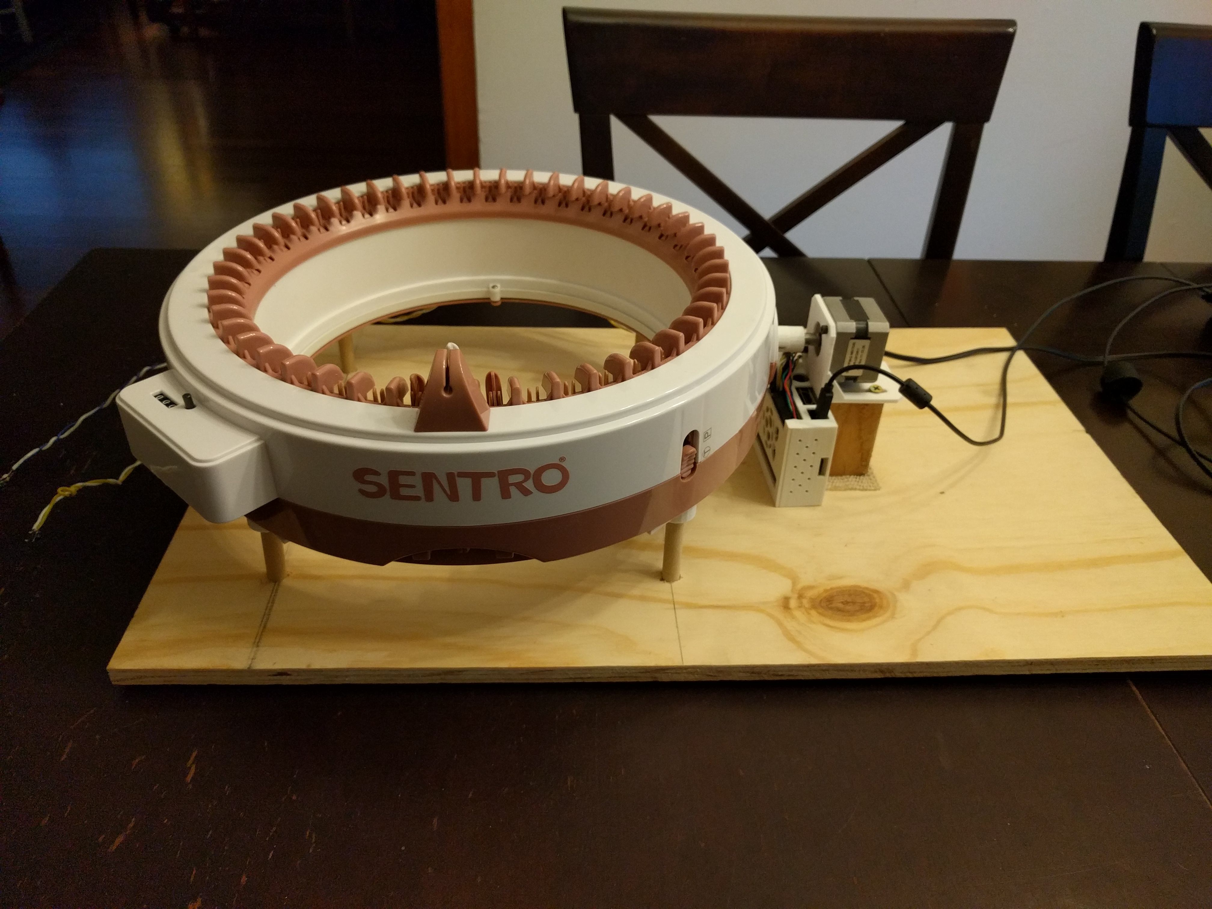
I originally started the project with a Sentro 48-hook knitting machine. This matched the number of hooks in the original project and it makes sense as a clock. Since each row was made up of 48 stitches, you simply do a stitch every half hour. The original plan was to mount it to a sturdy backer board and then build a simple birdhouse-style wooden frame to cover it.
One goal with this project was to ensure any changes I made to the knitting machine were reversible. One benefit of this mounting approach was that I could keep the knitting machine inside its original case, only replacing its plastic legs with wooden dowels. It only took about two weeks since starting the project before I had mounted everything to the backer board. I just needed to spend a few hours making the top wooden cover and the project would be done.
It was only after looking at everything mounted to its backer board that my wife and I agreed that it was simply too large to mount on the wall. Technically it would work, but aesthetically it wouldn't. The 48-hook machine was out.
Fortunately Sentro also makes a 22-hook knitting machine that is not only much smaller, but also about half the price. At first I tried to figure out how best to mount it to a smaller wooden backer board, but its plastic case presented a problem. Unlike the larger machine that had openings all around, this smaller machine only opened perpendicularly from the crank. Since I intended the crank to be at the top of the machine (so I could more easily hide it in the "roof" of the case), the plastic frame would block the fabric. It had to go.
Removing the mechanism from its case was a simple matter of removing the hand crank (pull out the center plug and remove a screw) and removing the four screws that hold the case together. After I removed the mechanism I realized that it was actually so small that it would easily fit on the print bed of my 3D printer. I already had to figure out some sort of frame to mount the mechanism to my case, and realized 3D printing one might actually be an option.
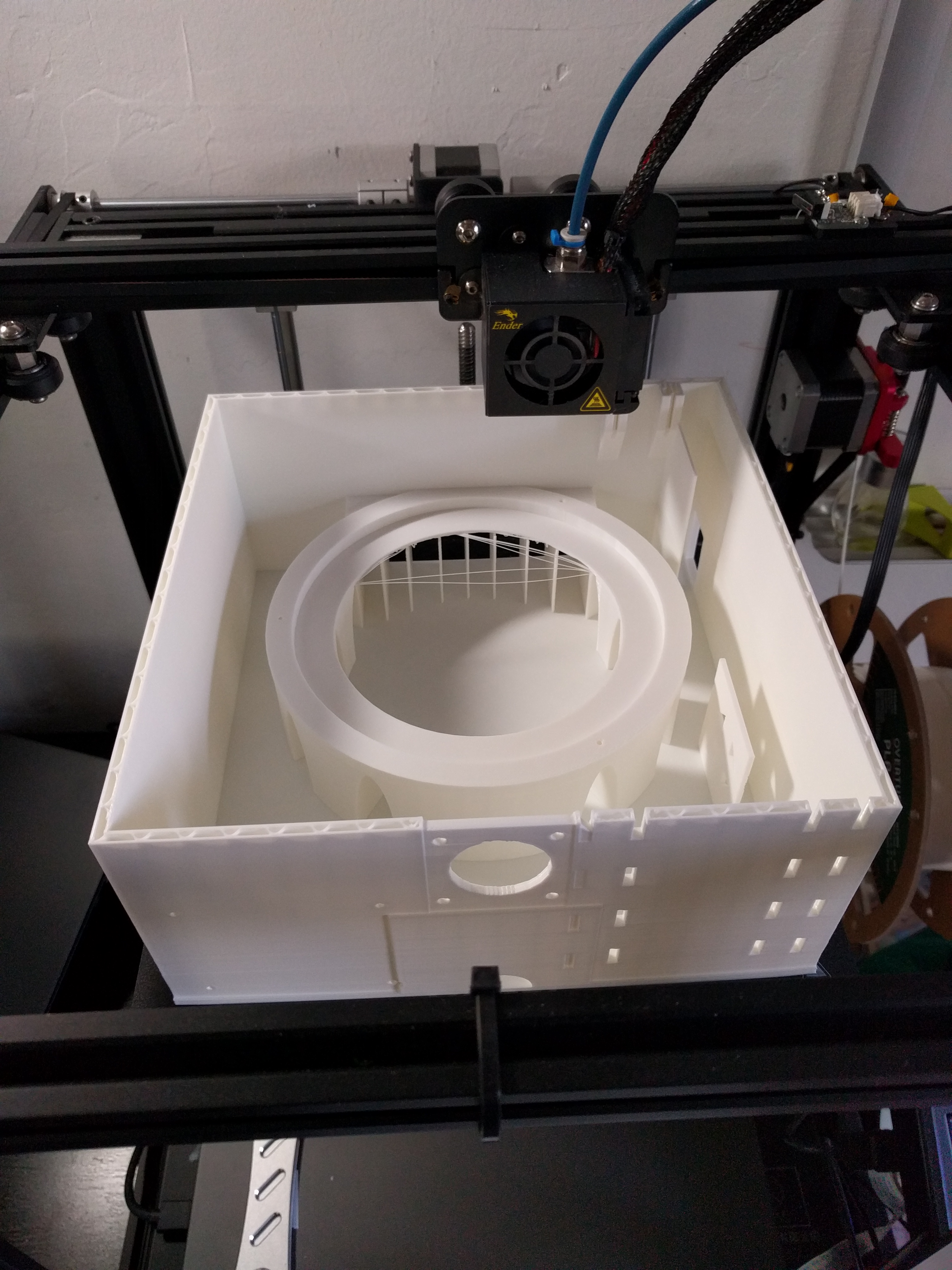
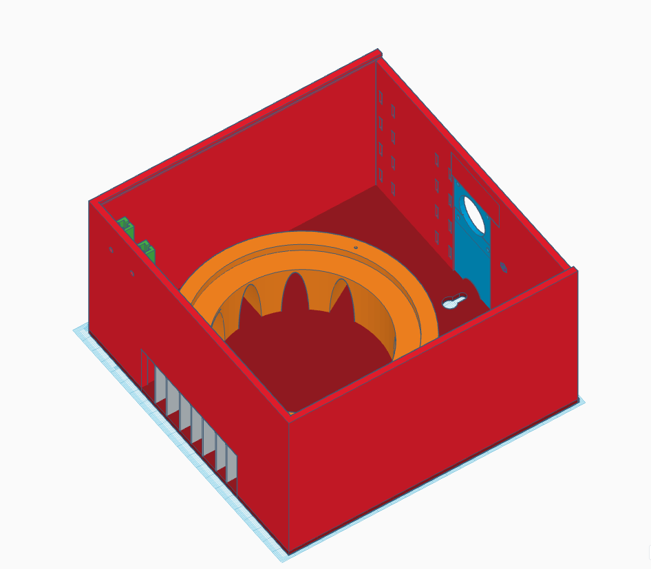
Originally the case was intended to be made of wood, because the 48-hook Sentro knitting machine was too large for anything else. I switched to the 22-hook Sentro machine and realized 3D printing a case was an option. Of course there was a problem: I didn't know anything about 3D modeling. Yes I've owned 3D printers for over a decade at this point, but I had always used parts from Thingiverse or Printables that someone else designed.
I had created an parent account on Tinkercad a few weeks prior so my son could learn 3D modeling, and had even used my account to make simple modifications to existing designs, such as increasing the size of a hole in the motor mount for my Sentro machine. What started as a three- to four-week project now became a two month project as I had to teach myself 3D modeling with Tinkercad and iterate through case designs. The bottom case alone took two days to print, and I ended up printing it at least three times over the course of the project as I discovered flaws in my design.
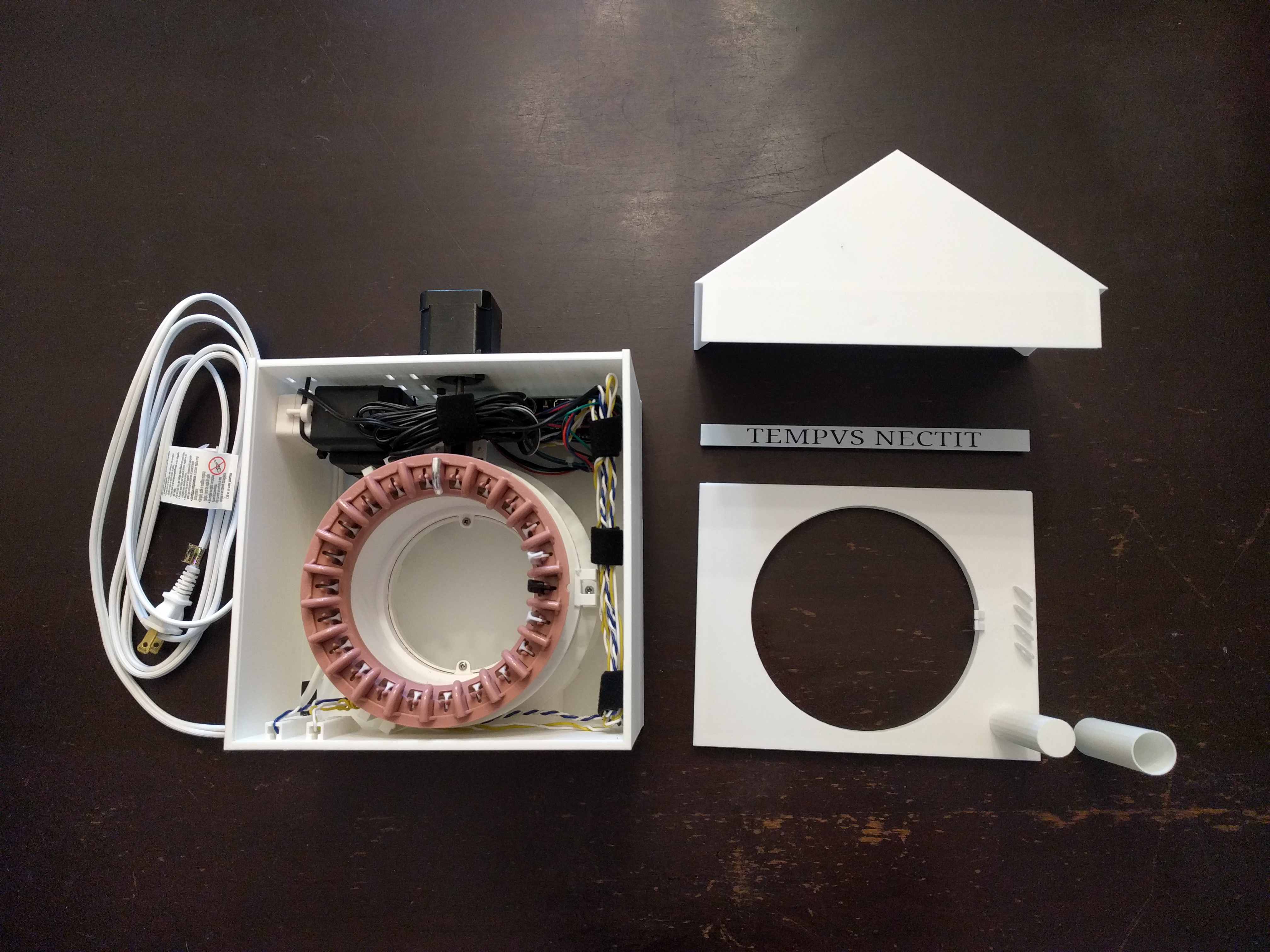
I decided the best approach was to mount everything to a large bottom case. At the top I would have little slots where I could slide in the top cover to cover the knitting machine and electronics, and provide a little house-like roof at the top to mimic other wall clock designs I had seen (including the inspiration for this project). Ultimately the top was split into three different objects, which had a few benefits:
- I could access the electronics and motor without disturbing knitting in progress
- I could orient each top case section when printing to reduce overhangs and the need for support material
- I could add a nice nameplate section that would double as a cover for the areas where the top case pieces joined together
Designing the case was an iterative process of measuring things carefully with calipers, figuring out how to create my ideas using Tinkercad, and printing out small sections of the bottom case (in particular the circular mounting point for the knitting machine) to test my measurements.
I ended up printing the bottom case (a 2-day print job) three times. The first time I didn't notice that my button mounting section had a 1mm gap between it and the side of the case. The second bottom case fixed that, but ended up being a bit too tall, as I needed the top case to press pretty firmly against the top ring of the knitting machine to hold it in place. I didn't discover this until after the two-day print was complete, I had mounted everything, and then started work on the top case. It was OK though, as there were other less important modifications I had wanted to make anyway.
In addition to the case sections, I also needed to design a few smaller parts: plastic button covers, small clips that would hold a gear ring on the knitting machine to the case, standoffs to mount the Raspberry Pi, and a spool to hold the yarn. You can see the full set of 3D printed objects on the project's Printables page.
Recommend
About Joyk
Aggregate valuable and interesting links.
Joyk means Joy of geeK