

In-orbit demonstration of an iodine electric propulsion system
source link: https://www.nature.com/articles/s41586-021-04015-y
Go to the source link to view the article. You can view the picture content, updated content and better typesetting reading experience. If the link is broken, please click the button below to view the snapshot at that time.

Abstract
Propulsion is a critical subsystem of many spacecraft1,2,3,4. For efficient propellant usage, electric propulsion systems based on the electrostatic acceleration of ions formed during electron impact ionization of a gas are particularly attractive5,6. At present, xenon is used almost exclusively as an ionizable propellant for space propulsion2,3,4,5. However, xenon is rare, it must be stored under high pressure and commercial production is expensive7,8,9. Here we demonstrate a propulsion system that uses iodine propellant and we present in-orbit results of this new technology. Diatomic iodine is stored as a solid and sublimated at low temperatures. A plasma is then produced with a radio-frequency inductive antenna, and we show that the ionization efficiency is enhanced compared with xenon. Both atomic and molecular iodine ions are accelerated by high-voltage grids to generate thrust, and a highly collimated beam can be produced with substantial iodine dissociation. The propulsion system has been successfully operated in space onboard a small satellite with manoeuvres confirmed using satellite tracking data. We anticipate that these results will accelerate the adoption of alternative propellants within the space industry and demonstrate the potential of iodine for a wide range of space missions. For example, iodine enables substantial system miniaturization and simplification, which provides small satellites and satellite constellations with new capabilities for deployment, collision avoidance, end-of-life disposal and space exploration10,11,12,13,14.
Spacecraft require propulsion to perform manoeuvres in space, such as orbit transfers, avoidance of collisions, orbit maintenance to compensate for aerodynamic or gravitational perturbations, and end-of-life disposal1. The choice of propulsion technology, in particular its exhaust speed, determines the propellant mass needed. Electric propulsion5,15 uses electric power to accelerate a propellant (via electric and/or magnetic fields) and can achieve exhaust speeds that are an order of magnitude higher than chemical propulsion (which uses energy from chemical reactions for propellant acceleration). Some of the most successful electric propulsion systems include gridded ion and Hall thrusters5, which create a plasma through electron impact ionization of a gas6 and electrostatically accelerate ions to generate thrust. In addition to being used by many commercial satellites orbiting the Earth, such propulsion systems are also used for space exploration. Examples include the European Space Agency’s SMART-1 mission to the Moon2, NASA’s Dawn mission that studied the protoplanets Ceres and Vesta in the asteroid belt between Mars and Jupiter16, and the Japanese Aerospace Exploration Agency’s Hayabusa1 and Hayabusa2 sample-return missions to the near-Earth asteroids 25143 Itokawa17 and 162173 Ryugu18.
As spacecraft are power limited, electric propulsion systems must maximize their thrust-to-power ratio, which for electrostatic accelerators requires a propellant with a low ionization threshold and a high atomic mass5. At present, the propellant of choice is xenon. However, xenon is very rare (less than one part per ten million in the atmosphere), and commercial production is both expensive and limited7,8,9. There are also competing applications that use xenon, including lighting and imaging, anaesthetics in hospitals9,19 and etching in the semiconductor industry20. With the rise of satellite mega-constellations21,22,23, thedemand for xenon may outpace supply within the next ten years. A further disadvantage is that xenon must be stored at very high pressures (typically 10–20 MPa), which requires specialized loading equipment and trained personnel, making it incompatible with the ‘new space’ paradigm. For the long-term sustainability of the space industry, it is critical that a replacement propellant be found.
A possible alternative is iodine24,25, which is much more abundant and cheaper than xenon26 (Methods) and can be stored unpressurized as a solid. In addition, both atomic and diatomic iodine have a lower ionization threshold, and diatomic iodine has a relative mass that is almost twice that of xenon. Although iodine is viewed as a game-changing propellant and has been investigated by companies27,28, universities29,30,31 and space agencies32 around the world, no system has previously been tested in space. Here we describe the development and testing of an iodine electric propulsion system (the NPT30-I2, with a nominal power and thrust of 55 W and 0.8 mN, respectively) and present results of the in-space operation of this new technology.
Solid diatomic iodine is stored in a tank connected to an inductively coupled plasma source tube terminated by two high-voltage, multi-aperture grids (Fig. 1). Heaters connected to the tank cause iodine sublimation and subsequent gas flow into the source tube. An iodine plasma is created by electron impact ionization using a radio-frequency (RF) inductive antenna, and positive plasma ions are extracted and accelerated by the grids to high speeds (about 40 km s−1) to produce thrust. A cathode filament downstream of the grids thermionically emits electrons to charge neutralize the ion beam. The propulsion system includes all subsystems for operation (Extended Data Fig. 1a), such as propellant storage, delivery and control, the gridded ion thruster, electron-emitting neutralizers, the power processing unit and passive thermal management33. See Methods for further details of the electrical system and cathode neutralizer. Iodine enables substantial miniaturization, and with the innovations discussed below, the total mass (including propellant) and volume are 1.2 kg and 96 mm × 96 mm × 106 mm, respectively.
Solid iodine (darker green region) is located in a storage tank upstream of the plasma source tube (blue region). Heating causes sublimation and a low-pressure gas (lighter green region) enters the source tube (green arrow). A plasma (purple region) is created by a RF antenna, and iodine ions (I+, I2+ and I2+) are accelerated by a set of grids. A cathode emits electrons (e−) to neutralize the ion beam. Waste heat is conducted towards the iodine tank and structural frame (solid blue arrows) or radiated away (blue dashed arrows).
The use of iodine creates unique design and operational challenges. Iodine has a high electronegativity that can lead to corrosion with many common materials. Technical ceramics (aluminium oxide and zirconium oxide) are used for the source tube and some interface components, and all vulnerable metal surfaces are coated with a polymer film. The iodine sublimation rate is controlled by monitoring and adjusting the tank temperature to maintain the desired saturation pressure in the range of 2–6 kPa. The operating temperature of the tank is kept between 80 °C and 100 °C to avoid local melting of iodine, and the tank is directly integrated upstream of the plasma source tube. When the propulsion system is not firing, iodine gas cools and deposits within a small orifice (Methods) between the tank and source tube blocking further flow without the need for a control valve.
Vibrations during launch and spacecraft motion once in orbit can cause solid iodine to break into pieces, which may damage the propulsion system or lead to poor thermal contact during heating. To prevent this, iodine is embedded into a porous aluminium oxide ceramic block with a porosity of 95% placed inside the tank (the tank-to-propellant mass fraction is 54%). During assembly, iodine is heated above its melting temperature to form a liquid, which is poured into the block (Methods). Once cooled, the iodine solidifies and is safely held. When thepropulsion system fires, plasma heat losses to the walls of the source tube and heat losses in the power electronics are directed towards the storage tank (Fig. 1). This allows reuse of waste heat so that less than 1 W of additional power is needed from heaters during steady-state operation. All other heat losses are channelled to the front and side panels of the propulsion system and either radiated or conducted to the spacecraft. See Methods for further thermal design details.
For plasma creation and ion acceleration, the use of iodine leads to important differences over xenon, as in addition to the molecular ion I2+, direct dissociative ionization29 and two-step dissociation and ionization reactions allow the formation of the atomic ion I+. Multiply charged ions, such as I2+, are also possible. Ground testing has been conducted to characterize the system before launch (Methods). Using time-of-flight spectrometry with an electrostatic diagnostic system in the thruster plume, mass-to-charge ratio spectra are measured (Fig. 2a) and the beam composition is determined, as shown in Fig. 2b. The dominant ion species are I2+ and I+, and their relative fractions change with RF generator output power. As the mass flow rate is fixed, higher iodine dissociation occurs at higher powers owing to an increased plasma density. Gas depletion at these powers also results in more energetic electrons, which affects the rate factors of collisional processes29.
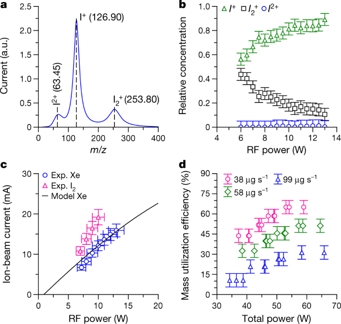
a, Example mass-to-charge ratio, m/z, spectrum obtained with the TOF diagnostic system. The labels indicate the ions I2+, I+ and I2+. b, Relative current concentration of iodine species in the ion beam as a function of RF generator output power. c, Ion-beam current extracted from the plasma source as a function of RF power with iodine and xenon propellants. The black curve shows results of a numerical plasma discharge model (Methods). d, Propellant mass utilization efficiency as a function of total power for different iodine mass flow rates. The error bars represent estimates of measuring equipment precision and accuracy limitations.
Despite diatomic gases having additional energy-loss mechanisms associated with molecular dissociation and the excitation of vibrational and rotational states34, the ionization efficiency of iodine in our propulsion system is higher than that of xenon, as shown in Fig. 2c. For the experiments with xenon, the system was temporarily modified to inject gas into the source tube from an external high-pressure storage tank. The iodine mass flow rate is inferred from measurements of the entire propulsion system mass before and after operation. In Fig. 2c, for the same mass flow rate and RF power, an almost 50%-higher beam current is extracted from the plasma source with iodine. This improvement is consistent with previous experimental and numerical results29,30 and occurs because of the lower ionization threshold of iodine ions (10.5 eV for I+ and 9.3 eV for I2+) compared with xenon (12.1 eV for Xe+) and the different collisional processes and reaction cross-sections. This results in a lower electron temperature and lower consequent plasma losses to the source tube walls34. The results for xenon are in agreement with a numerical model (Methods). A common ionization performance metric5,35 is the propellant mass utilization efficiency (Fig. 2d), ηm = \({\dot{m}}_{{\rm{i}}}/\dot{m}\), where \({\dot{m}}_{{\rm{i}}}\) is the ion mass flow rate and \(\dot{m}\) is the sublimation mass flow rate. At the highest performance in our system, ηm ≈ 60% for iodine and ηm ≈40% for xenon (not shown).
Ions in the plasma source are extracted and accelerated by voltages between 800 V and 1,300 V applied across the grids. Measurements of the ion flux distributions (Methods) in Fig. 3a confirm the presence of high-energy ions with an average energy close to the net accelerating voltage, Vn, of 900 V and 1,300 V, respectively. By measuring the ion-beam current (Methods) an indirect measurement of the thrust is obtained from, \(F=\alpha {\gamma I}_{{\rm{beam}}}\sqrt{2{M}_{{\rm{I}}}{V}_{{\rm{n}}}/{q}_{{\rm{I}}}}\). Here Ibeam is the beam current, MI and qI are the mass and charge of atomic iodine ions, respectively, and γ and α are correction factors: γ = cosθdiv, where θdiv is the beam divergence half-angle, and \(\alpha ={\beta }_{{{\rm{I}}}^{+}}+\sqrt{2}{\beta }_{{{\rm{I}}}_{2}^{+}}+{\beta }_{{{\rm{I}}}^{2+}}/\sqrt{2}\), where \({\beta }_{{{\rm{I}}}^{+}}\), \({\beta }_{{{\rm{I}}}_{2}^{+}}\) and \({\beta }_{{{\rm{I}}}^{2+}}\) are the relative current contributions for each ion species and the pre-factors represent the square root of the relative mass-to-charge ratio. An example of the thrust correction factor, αγ, is shown in Extended Data Fig. 3b. The propulsion system electronics continually perform these indirect thrust estimates during operation. Direct thrust measurements are obtained using a thrust balance (Methods). Figure 3b shows the measured thrust range achievable, and a comparison between direct and indirect measurements.
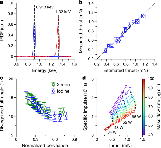
a, Ion flux distribution functions (IFDF) in the plume for acceleration voltages of 900 V and 1,300 V. b, Direct thrust measurements from a thrust balance compared with indirect thrust measurements estimated from the ion-beam current, applied grid voltage, and extrapolated beam divergence and beam composition data. c, Measured ion-beam divergence half-angle with iodine and xenon. The normalized perveance, p/pmax, is a measure of the ion space charge (Methods). d, Thrust and specific impulse performance map of the propulsion system within the operating total power range, and for different iodine mass flow rates. The error bars represent 1 s.d. (b) or estimates of measuring equipment precision and accuracy limitations (c).
By carefully designing the grids (Methods, Extended Data Fig. 3a, d), ions are well focused with a low divergence between 10° and 15°, as shown in Fig. 3c. The beam divergence has been measured with an automated array of electrostatic probes (Methods). The iodine divergence is slightly lower than that of xenon because of the improved ionization efficiency, which reduces unionized neutrals in the plume and lowers the ion-neutral collision frequency. An important performance metric is the specific impulse5, \({I}_{{\rm{sp}}}=F/\dot{m}{g}_{0}\), which represents how effectively propellant is used (here g0 is the gravitational acceleration equal to 9.81 m s−2). The performance map of the propulsion system is shown in Fig. 3d (see also Extended Data Fig. 3c, e), where the maximum thrust and specific impulse are about 1.3 mN and 2,500 s, respectively, for total powers (which includes RF power, acceleration power, neutralizer power, propellant heating power, electronics power and all losses) below 65 W. The total impulse that can be delivered to a spacecraft at the maximum specific impulse is 5,500 Ns (corresponding to a burn time of about 1,500 h).
The propulsion system has undergone extensive qualification to meet in-space conditions and launch-vehicle requirements (Methods), and a flight model was recently integrated into the Beihangkongshi-1 satellite operated by Spacety (Extended Data Fig. 1b). The 12-unit CubeSat (with a mass of approximately 20 kg) was launched into space onboard a Long March 6 rocket on 6 November 2020. The satellite was injected into a circular, Sun-synchronous orbit with an altitude of approximately 480 km.
Figure 4a summarizes all test firings performed up until 28 February 2021 and shows the mean semi-major axis of the satellite as predicted from a theoretical model, GPS data from the satellite, numerical simulations (using the General Mission Analysis Tool, GMAT36), and independent tracking data of the satellite (satellite catalogue number 46838) produced by the Space Surveillance Network (SSN) operated by the US Space Command37. The arrows indicate 11 firings over the displayed time period. Tests 1A and 1B represent firings to check the overall system operation. Subsequent firings 2A–2I test the repeatability and ignition cycling. The direction of the thrust vector has been varied during some firings (by reorienting the satellite using its onboard attitude control system). The duration of each test is between 80 min and 90 min (including 10–20 min for iodine heating and plasma ignition, which results in a small propellant mass loss of 12 mg before thrust generation), which for each firing gives an altitude change between 200 m and 400 m at a thrust and power of about 0.8 mN and 55 W, respectively. As an example, Fig. 4b shows GPS data, GMAT simulations and theoretical predictions for firing 1B, and Fig. 4c shows the estimated thrust and power consumption from telemetry data during the manoeuvre (see also Extended Data Fig. 4c). See Methods and Extended Data Table 1 for further orbital analysis details.
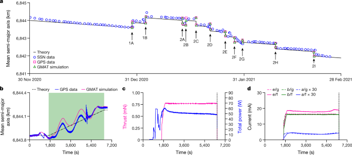
a, Mean semi-major axis of the Beihangkongshi-1 satellite from the SSN38 and GPS data, and as predicted using numerical simulations and theory. The arrows indicate separate firings. b, Mean semi-major axis as a function of time during manoeuvre 1B. The green region indicates when the propulsion system is firing. c, Thrust and total power telemetry during manoeuvre 1B. d, Comparison between ion-beam current, b, electron neutralizer current, e, and current to the accel grid, a, during ground, g, and in-flight, f, operation for manoeuvre 1B. The GPS data have an accuracy of approximately 20 m.
The results in Fig. 4a, b shows definite orbit changes correlated with the known propulsion system start times. At present, the firings have demonstrated a cumulative altitude change above 3 km. Additional downloaded propulsion system telemetry data are shown in Fig. 4d (see also Extended Data Fig. 4a, b), which is compared with corresponding ground measurement data taken during qualification. These measurements confirm that sufficient ion beam neutralization occurs (the electron emission current is larger than the ion current) and that ground testing conditions reproduce the space environment.
The linear decay between firings in Fig. 4a represents residual aerodynamic drag on the satellite1. Manoeuvres 1A and 1B demonstrate that the propulsion system can be used for orbit maintenance to compensate for this drag. In addition, all firings are representative of collision avoidance manoeuvres. Given the rapid growth of small satellites in low Earth orbit38, a miniaturized propulsion system enabled by the use of iodine will provide such satellites with the capability to avoid potential collisions and to deorbit at end of life to prevent the build-up of space debris: actions that will prove vital for the long-term sustainability of the space industry39.
In conclusion, we have described an iodine electric propulsion system and presented in-orbit results demonstrating this new technology. Our work shows that iodine is not only a viable replacement propellant for xenon but also gives enhanced performance. For large satellites and satellite constellations, the use of a more abundant propellant that can be stored unpressurized will help simplify satellite design and propulsion system integration and reduce the market demand for xenon, which may have benefits in other sectors9,24. For smaller satellites, iodine provides high impulse capability giving new options for deployment, collision avoidance and deorbiting, and advanced space exploration missions10,11,12,13,14.
Recommend
About Joyk
Aggregate valuable and interesting links.
Joyk means Joy of geeK