

kvm提高网卡效率使用SR-IOV
source link: https://bajie.dev/posts/20240115-kvm_sriov/
Go to the source link to view the article. You can view the picture content, updated content and better typesetting reading experience. If the link is broken, please click the button below to view the snapshot at that time.

Kvm提高网卡效率使用SR-IOV
什么是SR-IOV呢?
简单的说,SR-IOV是一种虚拟化方案,用来使一个PCIe的物理设备,能虚拟出多个设备,这些虚拟出来的设备看起来就像是多个真实的物理设备一样,并获得能够与本机性能媲美的 I/O 性能。
SR-IOV现在最多是用在网卡上,kvm虚拟机的网卡功能一般会下降到实体机的30-50%,如果改用SR-IOV会大大提高网卡性能。
SR-IOV 有2种功能:
- 物理功能 (Physical Function, PF)
- 就是标准的PCIe的功能了
- 虚拟功能 (Virtual Function, VF)
- 与物理功能关联的一种功能。VF 是一种轻量级 PCIe 功能,可以与物理功能以及与同一物理功能关联的其他 VF 共享一个或多个物理资源。VF 仅允许拥有用于其自身行为的配置资源。
好的,如何在生产环境中使用它呢?
场景如下:
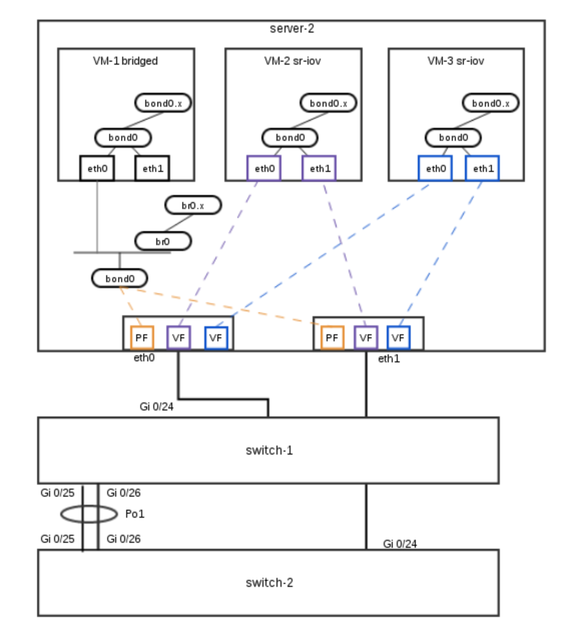
如上: 机房里有两台交换机:
- switch-1用来连接各机器的eth0口
- switch-2用来连接各机器的eth1口
- switch-1和switch-2互联
- 这是一种机房的标准连法,eth0和eth1做bonding,做线路冗余
server-2是一台Dell R730的服务器,eth0连switch-1,eth1连switch-2,上面跑了三个虚机:
- VM-1跑在基于bonding的Bridge上,标准的做法
- VM-2和VM-2则是利用了SR-IOV,从虚拟网卡直连到物理网卡,减少了中间环节,提高了网卡的效率。
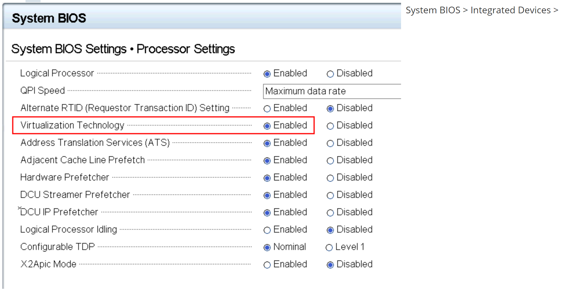
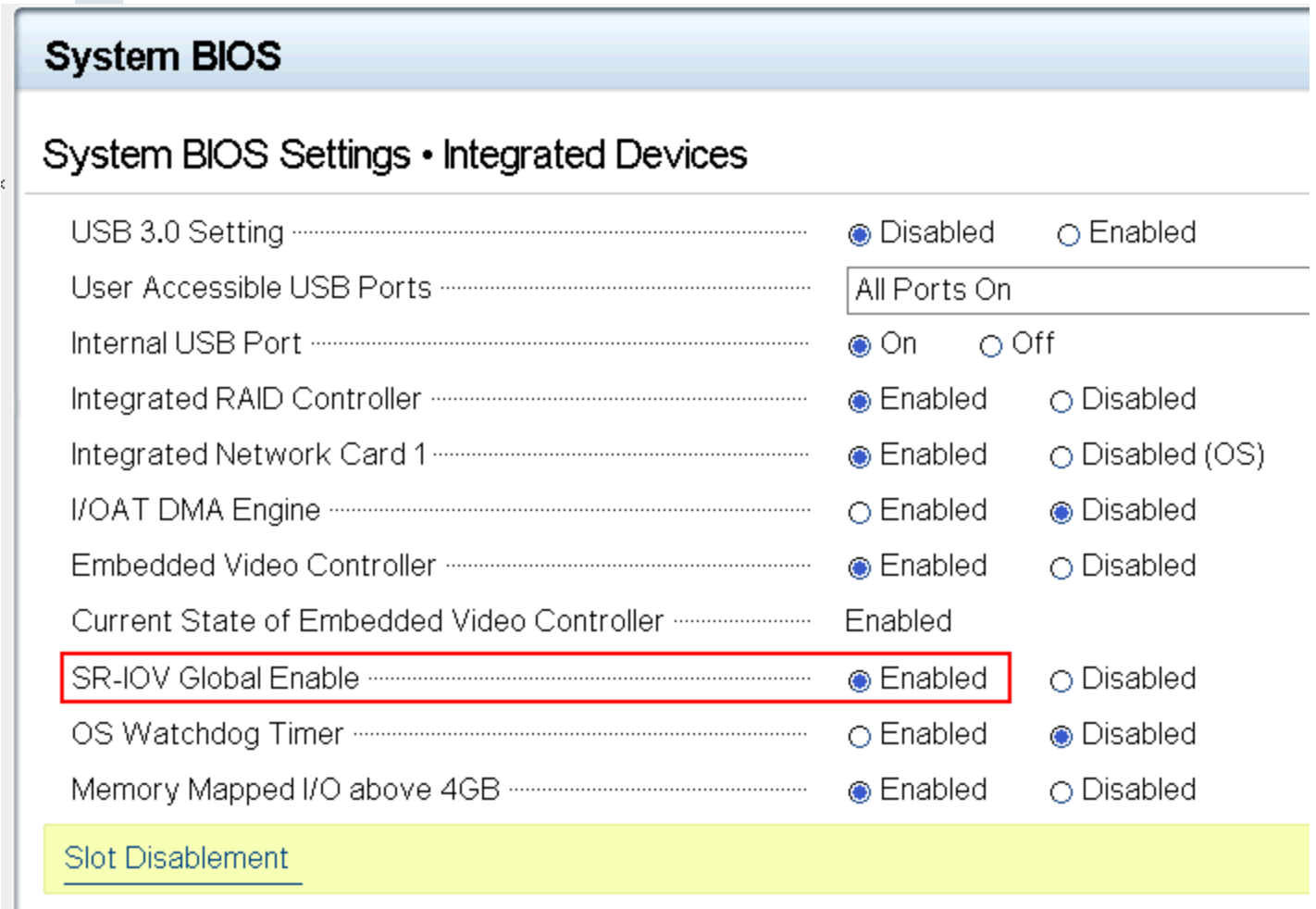
首先要把服务器的vt和sr-iov打开:
System BIOS > Processor Settings > Virtualization Technology
System BIOS > Integrated Devices > SR-IOV Global Enable
当然,这么麻烦的事情,我们直接用脚本通过idrac调用racadm来做好了:
#!/bin/sh
sshpass -p "xxxxx" ssh -oStrictHostKeyChecking=no [email protected].$1 racadm set BIOS.ProcSettings.ProcVirtualization Enabled
sshpass -p "calvin" ssh -oStrictHostKeyChecking=no [email protected].$1 racadm set BIOS.IntegratedDevices.SriovGlobalEnable Enabled
sshpass -p "xxxxxx" ssh -oStrictHostKeyChecking=no [email protected].$1 racadm serveraction powercycle
注意,Dell R730的机器用得是Intel I350的以太网卡,每个网口最多支持8个VF,如果是高级的X520网卡,就支持64个VF。
查看一下网卡,有以太网卡i350也有光卡82599ES:
lspci | grep net
01:00.0 Ethernet controller: Intel Corporation I350 Gigabit Network Connection (rev 01)
01:00.1 Ethernet controller: Intel Corporation I350 Gigabit Network Connection (rev 01)
19:00.0 Ethernet controller: Intel Corporation 82599ES 10-Gigabit SFI/SFP+ Network Connection (rev 01)
19:00.1 Ethernet controller: Intel Corporation 82599ES 10-Gigabit SFI/SFP+ Network Connection (rev 01)
82599ES 10G的卡,再看支持多少
cat /sys/class/net/em1/device/sriov_totalvfs
63
支持64个vfs
Centos 6编辑核心重启系统:
vi /boot/grub/grub.conf
kernel后加个参数intel_iommu=on
        kernel /vmlinuz-2.6.32-504.el6.x86_64 ro root=UUID=16154774-dbaf-4fcb-aedb-0513cb65a0eb rd_NO_LUKS rd_NO_LVM LANG=en_US.UTF-8 rd_NO_MD SYSFONT=latarcyrheb-sun16 crashkernel=auto  KEYBOARDTYPE=pc KEYTABLE=us rd_NO_DM rhgb quiet intel_iommu=on
Centos 7编辑核心重启系统:
kernel后加个参数,只虚两个网卡就好,intel_iommu=on ixgbe.max_vfs=2
vi /etc/default/grub
GRUB_CMDLINE_LINUX="crashkernel=auto rhgb quiet intel_iommu=on ixgbe.max_vfs=2"
grub2-mkconfig  -o /boot/grub2/grub.cfg
先lspci看看设备:
lspci
01:00.0 Ethernet controller: Intel Corporation I350 Gigabit Network Connection (rev 01)
01:00.1 Ethernet controller: Intel Corporation I350 Gigabit Network Connection (rev 01)
01:00.2 Ethernet controller: Intel Corporation I350 Gigabit Network Connection (rev 01)
01:00.3 Ethernet controller: Intel Corporation I350 Gigabit Network Connection (rev 01)
lspci -v
01:00.0 Ethernet controller: Intel Corporation I350 Gigabit Network Connection (rev 01)
    Subsystem: Dell Gigabit 4P I350-t rNDC
    Flags: bus master, fast devsel, latency 0, IRQ 46
    Memory at 91e00000 (32-bit, non-prefetchable) [size=1M]
    Memory at 91f0c000 (32-bit, non-prefetchable) [size=16K]
    Expansion ROM at 91f80000 [disabled] [size=512K]
    Capabilities: [40] Power Management version 3
    Capabilities: [50] MSI: Enable- Count=1/1 Maskable+ 64bit+
    Capabilities: [70] MSI-X: Enable+ Count=10 Masked-
    Capabilities: [a0] Express Endpoint, MSI 00
    Capabilities: [e0] Vital Product Data
    Capabilities: [100] Advanced Error Reporting
    Capabilities: [140] Device Serial Number ec-f4-bb-ff-ff-d9-96-43
    Capabilities: [150] Alternative Routing-ID Interpretation (ARI)
    Capabilities: [160] Single Root I/O Virtualization (SR-IOV)
    Capabilities: [1a0] Transaction Processing Hints
    Capabilities: [1c0] Latency Tolerance Reporting
    Capabilities: [1d0] Access Control Services
    Kernel driver in use: igb
    Kernel modules: igb
注意上面有一行表示是支持的: Capabilities: [160] Single Root I/O Virtualization (SR-IOV)
然后我们必须激活VFs,上面我们lspci查看四个I350网卡的usb id,em1是01:00.0,em2是01:00.1,em3是01:00.2,em4是01:00.4,激活em1和em2的VFs:
echo 7 >  /sys/bus/pci/devices/0000\:01\:00.0/sriov_numvfs
echo 7 >  /sys/bus/pci/devices/0000\:01\:00.0/sriov_numvfs
见鬼了,最大是8个,这里最多只能建7个。lspci看看,从第5行起,多了14个虚拟网卡(一个网卡7个):
lspci|grep I350
01:00.0 Ethernet controller: Intel Corporation I350 Gigabit Network Connection (rev 01)
01:00.1 Ethernet controller: Intel Corporation I350 Gigabit Network Connection (rev 01)
01:00.2 Ethernet controller: Intel Corporation I350 Gigabit Network Connection (rev 01)
01:00.3 Ethernet controller: Intel Corporation I350 Gigabit Network Connection (rev 01)
01:10.0 Ethernet controller: Intel Corporation I350 Ethernet Controller Virtual Function (rev 01)
01:10.1 Ethernet controller: Intel Corporation I350 Ethernet Controller Virtual Function (rev 01)
01:10.4 Ethernet controller: Intel Corporation I350 Ethernet Controller Virtual Function (rev 01)
01:10.5 Ethernet controller: Intel Corporation I350 Ethernet Controller Virtual Function (rev 01)
01:11.0 Ethernet controller: Intel Corporation I350 Ethernet Controller Virtual Function (rev 01)
01:11.1 Ethernet controller: Intel Corporation I350 Ethernet Controller Virtual Function (rev 01)
01:11.4 Ethernet controller: Intel Corporation I350 Ethernet Controller Virtual Function (rev 01)
01:11.5 Ethernet controller: Intel Corporation I350 Ethernet Controller Virtual Function (rev 01)
01:12.0 Ethernet controller: Intel Corporation I350 Ethernet Controller Virtual Function (rev 01)
01:12.1 Ethernet controller: Intel Corporation I350 Ethernet Controller Virtual Function (rev 01)
01:12.4 Ethernet controller: Intel Corporation I350 Ethernet Controller Virtual Function (rev 01)
01:12.5 Ethernet controller: Intel Corporation I350 Ethernet Controller Virtual Function (rev 01)
01:13.0 Ethernet controller: Intel Corporation I350 Ethernet Controller Virtual Function (rev 01)
01:13.1 Ethernet controller: Intel Corporation I350 Ethernet Controller Virtual Function (rev 01)
这时系统中会多出14个网卡:
ip link show
12: eth0: <BROADCAST,MULTICAST> mtu 1500 qdisc noop state DOWN qlen 1000
    link/ether ea:c0:8c:e1:e8:6d brd ff:ff:ff:ff:ff:ff
13: eth1: <BROADCAST,MULTICAST> mtu 1500 qdisc noop state DOWN qlen 1000
    link/ether e6:7f:65:3a:94:cf brd ff:ff:ff:ff:ff:ff
14: eth2: <BROADCAST,MULTICAST> mtu 1500 qdisc noop state DOWN qlen 1000
    link/ether a2:39:5e:a7:5c:17 brd ff:ff:ff:ff:ff:ff
15: eth3: <BROADCAST,MULTICAST> mtu 1500 qdisc noop state DOWN qlen 1000
    link/ether 9a:dd:4a:14:87:48 brd ff:ff:ff:ff:ff:ff
16: eth4: <BROADCAST,MULTICAST> mtu 1500 qdisc noop state DOWN qlen 1000
    link/ether 2a:07:15:af:44:1c brd ff:ff:ff:ff:ff:ff
17: eth5: <BROADCAST,MULTICAST> mtu 1500 qdisc noop state DOWN qlen 1000
    link/ether 42:6c:7c:11:1f:40 brd ff:ff:ff:ff:ff:ff
18: eth6: <BROADCAST,MULTICAST> mtu 1500 qdisc noop state DOWN qlen 1000
    link/ether 86:5f:69:12:48:56 brd ff:ff:ff:ff:ff:ff
19: eth7: <BROADCAST,MULTICAST> mtu 1500 qdisc noop state DOWN qlen 1000
    link/ether 72:d7:d0:0a:6a:86 brd ff:ff:ff:ff:ff:ff
20: eth8: <BROADCAST,MULTICAST> mtu 1500 qdisc noop state DOWN qlen 1000
    link/ether 22:4f:16:83:40:83 brd ff:ff:ff:ff:ff:ff
21: eth9: <BROADCAST,MULTICAST> mtu 1500 qdisc noop state DOWN qlen 1000
    link/ether 1e:a1:10:50:82:cd brd ff:ff:ff:ff:ff:ff
22: eth10: <BROADCAST,MULTICAST> mtu 1500 qdisc noop state DOWN qlen 1000
    link/ether de:d7:35:6f:8a:8b brd ff:ff:ff:ff:ff:ff
23: eth11: <BROADCAST,MULTICAST> mtu 1500 qdisc noop state DOWN qlen 1000
    link/ether ce🆎e1:81:0e:31 brd ff:ff:ff:ff:ff:ff
24: eth12: <BROADCAST,MULTICAST> mtu 1500 qdisc noop state DOWN qlen 1000
    link/ether d6:35:8e:ed:d9:1d brd ff:ff:ff:ff:ff:ff
25: eth13: <BROADCAST,MULTICAST> mtu 1500 qdisc noop state DOWN qlen 1000
    link/ether 52:c5:00:45:74:2c brd ff:ff:ff:ff:ff:ff
定义两个网络池,只要指定指定pf即可,vf会动态分配给虚机:
cat net01.xml
<network>
  <name>passthrough_em1</name>
  <forward mode='hostdev' managed='yes'>
    <pf dev='em1'/>
  </forward></network>
</network>

cat net02.xml
<network>
  <name>passthrough_em2</name>
  <forward mode='hostdev' managed='yes'>
    <pf dev='em2'/>
  </forward></network>
</network>
启动这2个网络:
virsh net-define net01.xml
virsh net-start passthrough_em1
virsh net-autostart passthrough_em1

virsh net-define net02.xml
virsh net-start passthrough_em2
virsh net-autostart passthrough_em2

modprobe vfio
我们编辑虚机的xml配置文件
...
    <interface type="network">
      <source network="passthrough_em1"/>
    </interface>
    <interface type="network">
      <source network="passthrough_em2"/>
    </interface>
...
ok, 启动虚机即可。
注意,em1和em2的bonding参数,在实体机和虚机中的bonding配置是一样的:
BONDING_OPTS="miimon=80 mode=1 primary=eth0 updelay=30000"
为避免频繁切换,updelay设置为30秒
例外: 实机和虚机的bonding是一样的,如果实机网卡eth0坏了,eth1接管,那么虚机中同样也会飘到eth1。这里有个问题,如果网卡处于bonding状态,那么所有的网卡的mac地址都是一样的,如果eth0挂了,那么bongding的驱动程序会去改变eth1的mac地址,把老的eth0的地址赋给eth1,在实体机上,mac都一样,所以会拒绝,但是在虚机上却会成功,这样就导致虚机和实机在同一个网卡上有两个不同的mac地址,发到虚机上eth1的包会被当成mac spoof而被丢掉。
解决方法是bonding参数加上failovermac=active 或者设置spoofchk off,得把所有虚拟vf都弄一遍
 ip link set em1 vf 1 spoofchk off
 ...
 ip link set em1 vf 7 spoofchk off
Recommend
About Joyk
Aggregate valuable and interesting links.
Joyk means Joy of geeK