

Raspberry Pi 5 and RP1 X-ray scans
source link: https://www.jeffgeerling.com/blog/2023/raspberry-pi-5-and-rp1-x-ray-scans
Go to the source link to view the article. You can view the picture content, updated content and better typesetting reading experience. If the link is broken, please click the button below to view the snapshot at that time.

Raspberry Pi 5 and RP1 X-ray scans
Following up on my X-ray scans of the Raspberry Pi Zero 2 W two years ago, I had the opportunity to scan the Raspberry Pi 5, working with an electronics inspection lab:
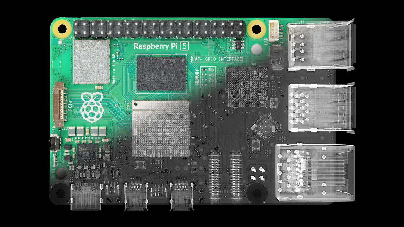
I posted a video detailing everything I imaged on the board, but in this blog post, I'll hit on the highlights—the new chips at the heart of the Pi 5: the BCM2712 SoC and the RP1 'southbridge'.
Aside: If you are Casetify, then yes, I have retouched these images in a couple extremely minor ways to ensure I have digital provenance 😘.
Oh, and I'm selling a Pi 5 X-ray tee shirt and hoodie.
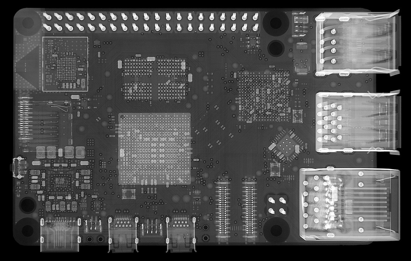
The board layout has some radical departures from the earlier Pi 4—besides the Ethernet port and PoE pins swapping sides back to a Pi 3 and earlier arrangement, the majority of the middle of the board is dominated by expanded IO: 5 total PCIe lanes, LPDDR4x memory channels, and HDMI signals all routed through the SoC.
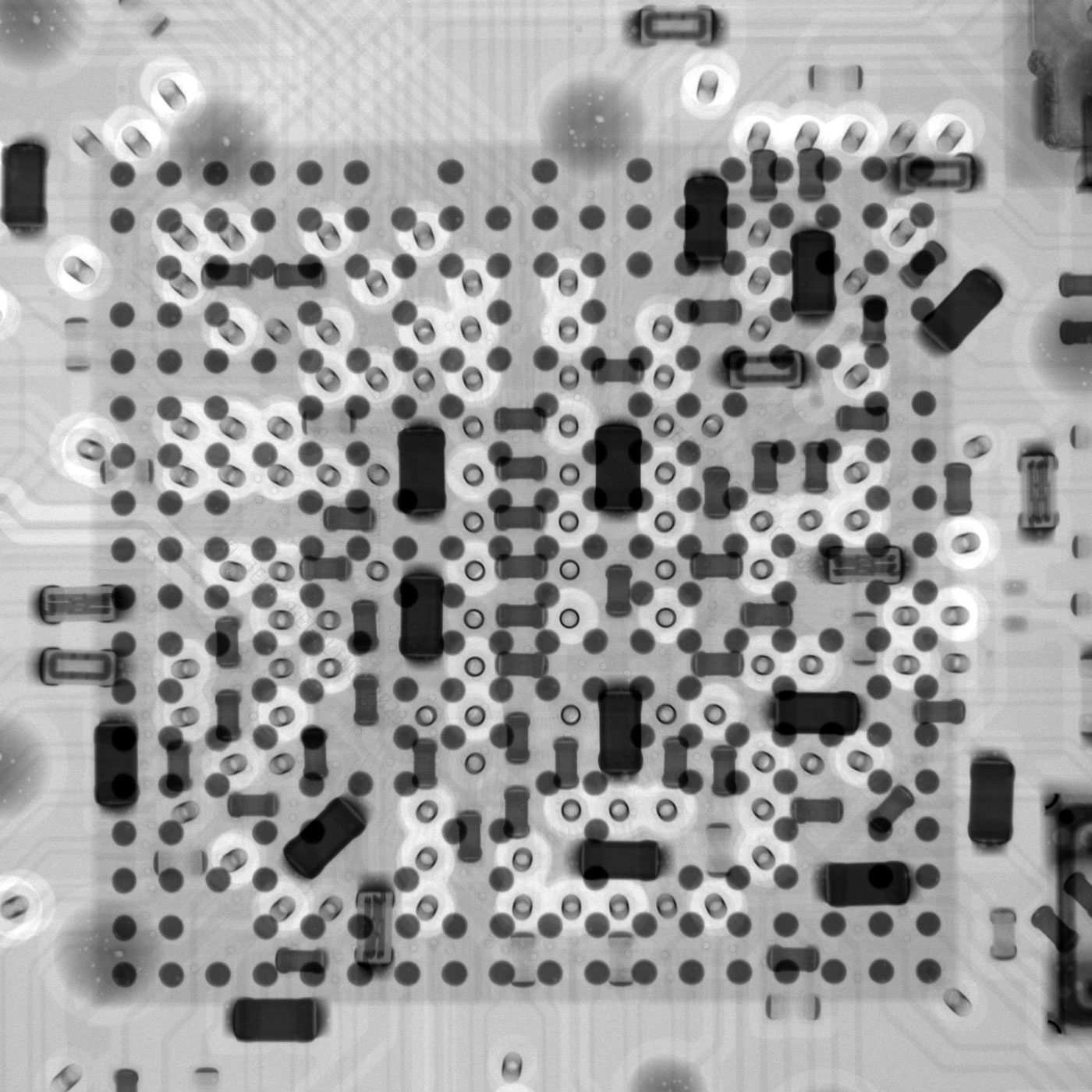
BCM2712 Arm SoC
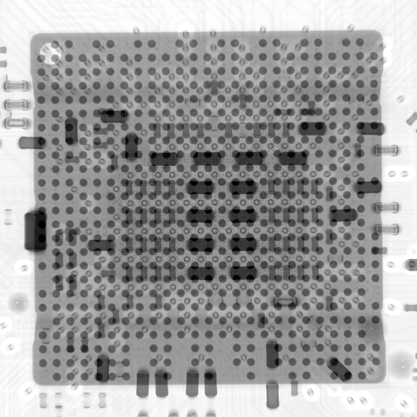
The SoC at the heart of the Pi 5 is a new BCM2712 chip from Broadcom, with a VideoCore VII GPU and four Arm A72 CPU cores clocked at 2.4 GHz.
The package is much smaller than the total package dimension, and you can just make out some of the bonding wires around it in the image above.
I counted all the package solder balls so you don't have to—there are 586 pins coming off the BCM2712 (in a 25 x 25 BGA, with some pads empty). Those pins route signals to and from all parts of the Pi, but besides the dual 4K60-capable HDMI ports, a lot of that signaling goes through the 4 PCI Express lanes attached to the RP1 chip.
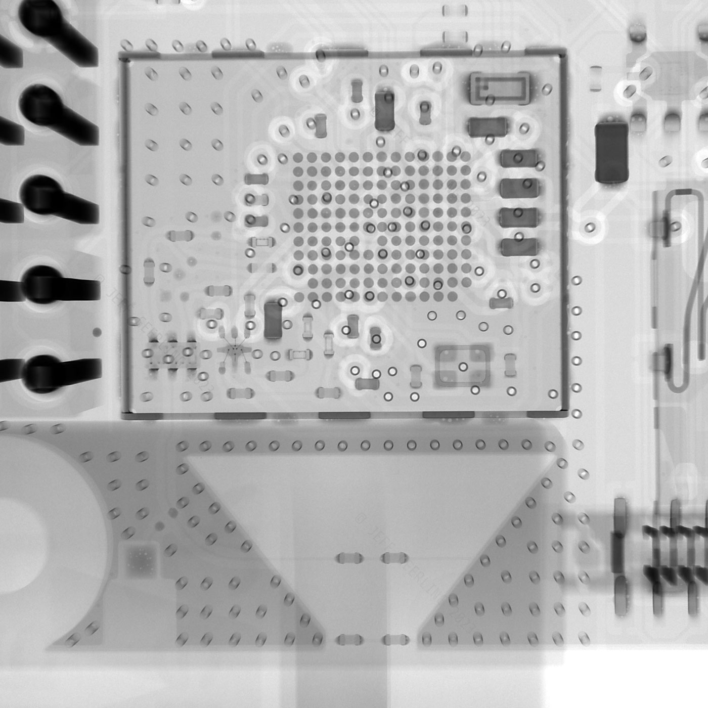
RP1 Southbridge
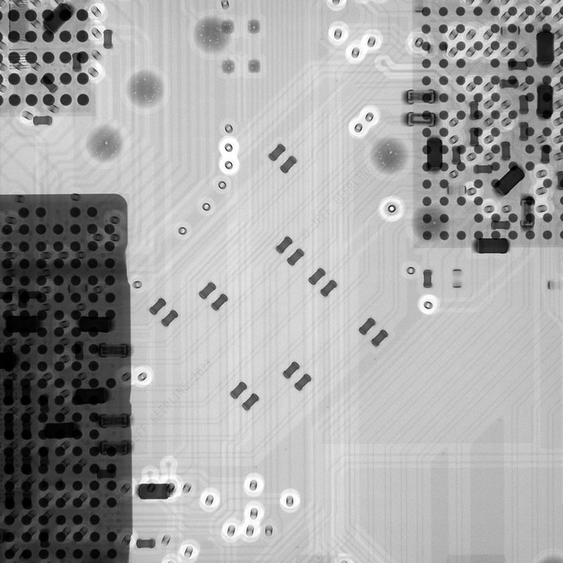
Those lanes form a little '8-lane highway' on the surface of the Pi's PCB, with each differential pair holding a tiny set of capacitor 'cars' at one point or another along the route, making the highway analogy complete.
The RP1 itself is less than a quarter the size of the full package, with 265 total pins in its BGA, laid out in an 18 x 18 grid.
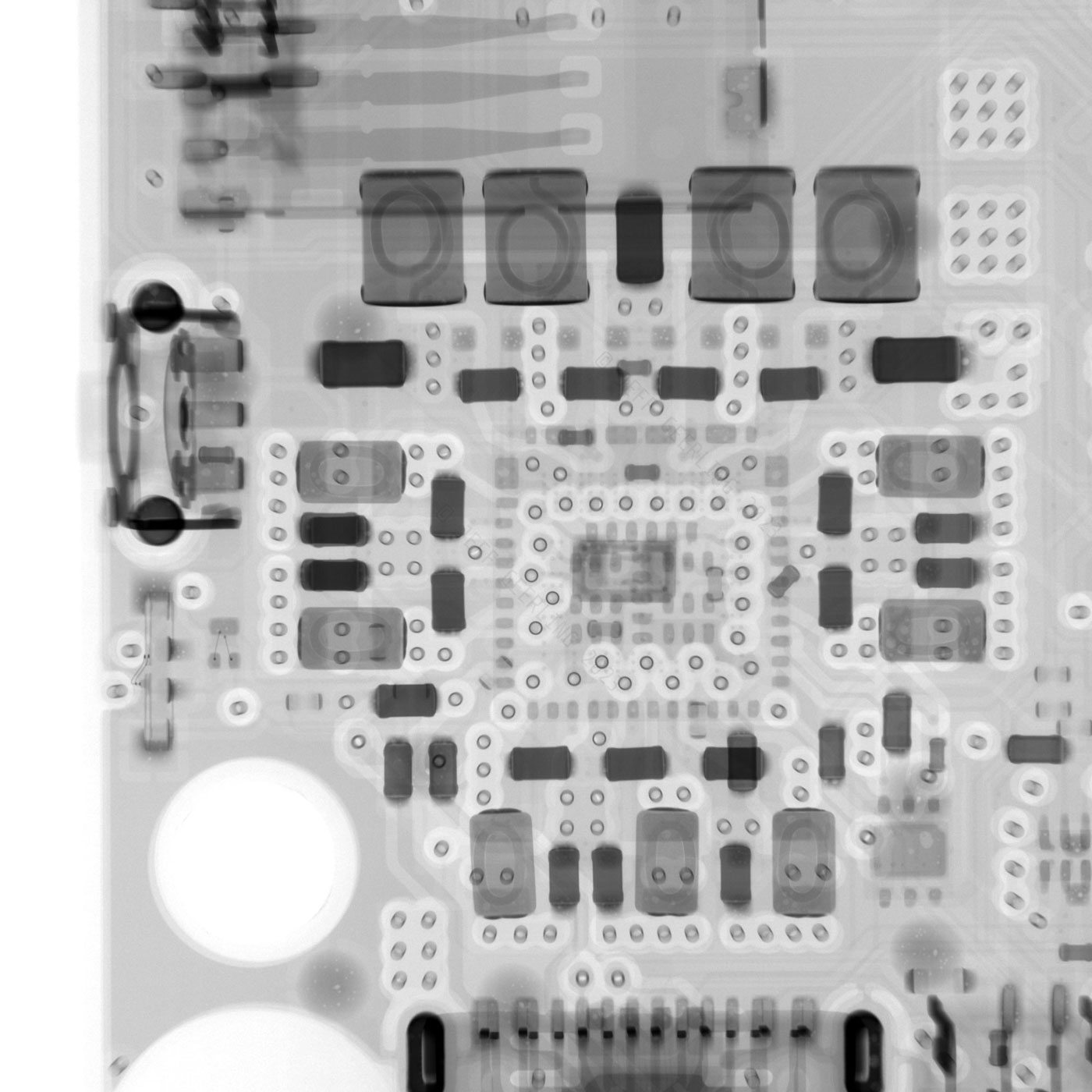
Other tidbits
There are a few other parts of the board that were especially interesting, like the integrated WiFi antenna cut into the PCB itself:
And also the new (and somewhat controversial) 5V 5A board power supply:
To see the rest of the X-ray images, please watch the video over on my YouTube channel. I hope to get more posted up in full resolution at some point, maybe on Flickr or another blog post, but for now, the full set is visible in that video.
Recommend
-
29
Detecting COVID-19 symptoms through Artificial Intelligence
-
10
Web vulnerability scans have slowed down Just like the raptors in the original Jurassic Park, there are automated scanners which are "testing the fences for weaknesses". Check this out: [26/Apr/2012:10:51:42 -...
-
6
Implementing perimeter security scans on cloud infrastructure Vytautas Paulauskas Uncover cloud infrastructure security issues with perimeter scans
-
6
The Internet Archive has enhanced its Computerworld scans Preserving the rapid rise of technology By
-
8
Business Trends
-
11
What Brain Scans Can Tell You — And What They CannotShedding Some Light On The Brain Scans Crisis
-
8
Are Index Scans Bad? The answer No. Index Scans are Not Always Bad. This was in-depth discussed with my client during the Comprehensive Database...
-
5
Intro You can get official DPT-RP1 support while using Windows or MacOS. Sony has a well-designed software Digital Paper App, which supports everything in the user manual. Unfortunately, Sony do not support Linux. And the prog...
-
4
RP1: A Brief Introduction
-
2
LAXCUS分布式操作系统6.0 RP1版本发布 原创 LAXCUS分布式操作系统 2022-...
About Joyk
Aggregate valuable and interesting links.
Joyk means Joy of geeK