

硬件通信:串口、I2C、SPI、I2S 开发例程
source link: https://www.51cto.com/article/751392.html
Go to the source link to view the article. You can view the picture content, updated content and better typesetting reading experience. If the link is broken, please click the button below to view the snapshot at that time.

硬件通信:串口、I2C、SPI、I2S 开发例程

一、硬件通信
1、串口通信
(1)Uart函数接口
涉及串口相关的函数主要是初始化、发送/读取数据、去初始化函数整理如下:
IoTUartInit(unsigned int id, const IotUartAttribute *param) | 初始化指定的UART端口id: 表示UART设备的端口号param:表示指向UART属性的指针 | //base/iot_hardware/peripheral/interfaces/kits/iot_uart.h |
IoTUartRead(unsigned int id, unsigned char *data, unsigned int dataLen) | 从UART设备中读取指定长度的数据id: 表示UART设备的端口号data: 表示指向要读取数据的起始地址的指针dataLen: 表示要读取的字节数 | //base/iot_hardware/peripheral/interfaces/kits/iot_uart.h |
IoTUartWrite(unsigned int id, const unsigned char *data, unsigned int dataLen) | 将指定长度的数据写入UART设备 | //base/iot_hardware/peripheral/interfaces/kits/iot_uart.h |
IoTUartDeinit(unsigned int id) | 去初始化指定的UART端口 | /base/iot_hardware/peripheral/interfaces/kits/iot_uart.h |
另外,查看iot_uart.h文件可知,其只是对hi_uart.h中定义的函数进行了再一次封装,hi_uart.h中还定义了限时读取函数:
/**
* @ingroup  iot_uart
* @brief  Reads data in specified timeout time.CNomment:在指定超时时间内读取数据。CNend
*
* @par 描述:
*           Reads data in specified timeout time.CNomment:在指定超时时间内读取数据。CNend
*           if Reads all data before timeout, function will return.
CNomment:超时前读取完成所有数据后,函数会立即返回。CNend
*
* @attention This API must be used after the hi_uart_open function is called.
CNcomment:须在调用完hi_uart_init函数之后使用。CNend
* @param  id        [IN] type #hi_uart_idx,UART port id. CNcomment:UART端口号。CNend
* @param  data      [OUT] type #hi_u8*,Start address of the data to be read.CNcomment:读到数据的首地址。CNend
* @param  data_len  [IN] type #hi_u32,Number of bytes to be read.CNcomment:要读取数据的字节数。CNend
* @param  timeout_ms  [IN] type #hi_u32,timeout.CNcomment:超时时间。CNend
*
* @retval #>=0 Number of bytes that are actually read.CNcomment:实际读到数据的字节数。CNend
* @retval #HI_ERR_FAILURE  Data read error.CNcomment:读数据失败。CNend
* @par 依赖:
*            @li hi_uart.h:Describes UART APIs.CNcomment:UART相关接口。CNend
* @see  hi_uart_write。
*/
hi_s32 hi_uart_read_timeout(hi_uart_idx id, hi_u8 *data, hi_u32 len, hi_u32 timeout_ms);
串口主要参数有波特率、串口号、奇偶校验等使用一个IotUartAttribute结构体定义,iot_uart.h中具体定义如下:
/**
 * @brief Defines basic attributes of a UART port.
 *
 * @since 2.2
 * @version 2.2
 */
typedef struct {
    /** Baud rate */
    unsigned int baudRate;
    /** Data bits */
    IotUartIdxDataBit dataBits;
    /** Stop bit */
    IotUartStopBit stopBits;
    /** Parity */
    IotUartParity parity;
    /** Rx block state */
    IotUartBlockState rxBlock;
    /** Tx block state */
    IotUartBlockState txBlock;
    /** Padding bit */
    unsigned char pad;
} IotUartAttribute;
(2)串口蓝牙案例
下面我们做一个简单的串口通信实验,将一串自定义数据通过Hi3861的UART1发送到蓝牙模块(或者其他开发板)。开发流程有以下几步:配置并开启串口、编写发送\读取任务逻辑、开启任务线程、编译运行测试。
开发准备:两块hi3861开发板或者hi3861开发板和带串口的设备(如HC05串口蓝牙模块)
- 第一步:配置并开启串口。在iothardware下新建文件uart_bluetooth.c文件。由于默认UART 0为调试串口对应的是GPIO03和GPIO04,一般情况下不修改;与其他设备通信使用UART 1或者UART 2,本实验使用的是UART1,对应的就是GPIO00(UART1的TX)和GPIO01(UART1的RT),首先我们将GPIO0、GPIO1的复用为串口,波特率设置为115200,8个数据位,1个停止位,无校验。具体实现如下:
#define BLUE_RX_1 1
#define BLUE_TX_0 0
int Bluetooth_Init()
{
    // 初始化GPIO
    IoTGpioInit(HI_IO_NAME_GPIO_0);
    hi_io_set_func(BLUE_TX_0, HI_IO_FUNC_GPIO_0_UART1_TXD);
    IoTGpioInit(HI_IO_NAME_GPIO_1);
    hi_io_set_func(BLUE_RX_1, HI_IO_FUNC_GPIO_1_UART1_RXD);

    // 配置UART 1参数
    IotUartAttribute my_param; //={115200,8,1,HI_UART_PARITY_NONE,0,0};
     /** Baud rate */
    my_param.baudRate=115200;
    /** Data bits */
    my_param.dataBits=8;
    /** Stop bit */
    my_param.stopBits=1;
    /** Parity */
    my_param.parity=HI_UART_PARITY_NONE;
    return  IoTUartInit(HI_UART_IDX_1, &my_param);
}- 第二步:编写发送\读取任务逻辑。测试逻辑较为简单,先将字符串“Hello OpenHarmony”发送出去,然后调用读取接口获取读到的数据。具体实现如下:
// 串口蓝牙数据交互
static void BluetoothTask(void *arg)
{
    char send_data[] = "Hello OpenHarmony";
    IoTUartWrite(HI_UART_IDX_1, (unsigned char*)send_data, strlen(send_data));

    char get_data[8] = {0};
    int data_len = 8;
    while (1)
    {
        usleep(500000); // 0.5s
        ret = IoTUartRead(HI_UART_IDX_1, get_data, data_len);
        if (ret == 0)
            printf("get_data = %s\n", get_data);
        else
            printf("get_data Falile\r\n");
    }
}- 第三步:开启任务线程。开启串口任务线程和前面几节实验教程类似,这里给出蓝牙实验uart_bluetooth.c完整代码:
#include <stdio.h>
#include <unistd.h>
#include "ohos_init.h"
#include "cmsis_os2.h"

#include <string.h>
#include "hi_io.h"  // 定义了GPIO编号、描述GPIO功能
#include "hi_uart.h"
#include "iot_uart.h"

#define BLUE_RX_1 1
#define BLUE_TX_0 0

int Bluetooth_Init()
{
    // 初始化GPIO
    IoTGpioInit(HI_IO_NAME_GPIO_0);
    hi_io_set_func(BLUE_TX_0, HI_IO_FUNC_GPIO_0_UART1_TXD);
    IoTGpioInit(HI_IO_NAME_GPIO_1);
    hi_io_set_func(BLUE_RX_1, HI_IO_FUNC_GPIO_1_UART1_RXD);

    // 配置UART 1参数
    IotUartAttribute my_param; //={115200,8,1,HI_UART_PARITY_NONE,0,0};
     /** Baud rate */
    my_param.baudRate=115200;
    /** Data bits */
    my_param.dataBits=8;
    /** Stop bit */
    my_param.stopBits=1;
    /** Parity */
    my_param.parity=HI_UART_PARITY_NONE;
    return  IoTUartInit(HI_UART_IDX_1, &my_param);
}
//测试蓝牙
static void BluetoothTask(void *arg)
{
    (void)arg;
    sleep(2);
    int ret = 1;
    ret = Bluetooth_Init();
    if (ret != 0)
    {
        printf("Uart1 init failed! \n");
        return;
    }
    char send_data[] = "Hello OpenHarmony";
    IoTUartWrite(HI_UART_IDX_1, (unsigned char*)send_data, strlen(send_data));

    char get_data[8] = {0};
    int data_len = 8;
    while (1)
    {
        usleep(500000); // 0.5s
        ret = IoTUartRead(HI_UART_IDX_1, get_data, data_len);
        if (ret == 0)
            printf("get_data = %s\n", get_data);
        else
            printf("get_data Falile\r\n");
    }
}

static void BluetoothDemo(void)
{
    osThreadAttr_t attr;
    attr.name = "BluetoothTask";
    attr.attr_bits = 0U;
    attr.cb_mem = NULL;
    attr.cb_size = 0U;
    attr.stack_mem = NULL;
    attr.stack_size = 4096;
    attr.priority = osPriorityNormal;
    if (osThreadNew(BluetoothTask, NULL, &attr) == NULL)
    {
        printf("[BlueDemo] Falied to create BluetoothTask!\n");
    }
}
APP_FEATURE_INIT(BluetoothDemo);- 第四步:编译运行测试。因为我们的工程在iothardware目录下,所以只需修改该目录下的BUILD.gn文件,添加我们的工程即可,修改如下:
static_library("led_example") {
    sources = [
        # "led_example.c",
        # "gpio_input_output.c",
        # "gpio_adc.c",
        # "gpio_pwm.c",
        "uart_bluetooth.c",
    ]
    include_dirs = [
        "//utils/native/lite/include",
        "//kernel/liteos_m/kal/cmsis",
        "//base/iot_hardware/peripheral/interfaces/kits",
        "//device/hisilicon/hispark_pegasus/sdk_liteos/include",
    ]
}
连接蓝牙模块(或者串口模块)RT、TX要交叉。我这里连接了HC05蓝牙模块,然后使用手机连接蓝牙,互相发送数据。测试效果如下:
(3)串口使用注意事项
- 接收经常卡死怎么办: 使用hi_uart_read_timeout(在 hi_uart.h中)
- 使用多个串口 :同时使用多个串口在实际使用中可能会遇到无法读取数据或者卡死状态(阻塞了),这里有两个解决方案:开启多线程(不同线程开启不同串口)、读取数据用限时读取hi_uart_read_timeout()
2、I2C通信
(1)I2C函数接口
I2C是常用硬件接口,MPU6050、温湿度传感器等会使用到。I2C的原理可见Analog Dialogue I2C。I2C相关函数接口整理如下:
IoTI2cInit(unsigned int id, unsigned int baudrate) | 以指定的波特率初始化I2C设备。id:I2C设备ID baudrate:指定的I2C波特率 | //base/iot_hardware/peripheral/interfaces/kits/iot_i2c.h |
IoTI2cWrite(unsigned int id, unsigned short deviceAddr, const unsigned char *data, unsigned int dataLen) | 将数据写入I2C设备 | //base/iot_hardware/peripheral/interfaces/kits/iot_i2c.h |
IoTI2cRead(unsigned int id, unsigned short deviceAddr, unsigned char *data, unsigned int dataLen); | 从I2C设备读取数据 | //base/iot_hardware/peripheral/interfaces/kits/iot_i2c.h |
IoTI2cSetBaudrate(unsigned int id, unsigned int baudrate) | 设置I2C设备的波特率 | //base/iot_hardware/peripheral/interfaces/kits/iot_i2c.h |
上述IoTI2cRead、IoTI2cWrite实质是分别把hi_i2c_wirte()、hi_i2c_read()函数进行一层封装,实际建议直接使用hi_i2c_wirte()、hi_i2c_read() 【在hi_i2c.h文件中有定义编写程序,发送数据更灵活一些。
另外,在hi_i2c.h中定义了发送的数据类型,可以看到是一个结构,接收时可以不用指定send_buf、send_len两个变量,同理发送时可以不用指定另外两个变量。
/**
 * @ingroup iot_i2c
 *
 * I2C TX/RX data descriptor. CNcomment:I2C发送/接收数据描述符。CNend
 */
typedef struct {
    hi_u8*  send_buf;        /**< Data TX pointer. The user needs to ensure that no null pointer is transferred.
                                CNcomment:数据发送指针CNend */
    hi_u32  send_len;        /**< Length of sent data (unit: byte).
                                CNcomment:发送数据长度(单位:byte)CNend */
    hi_u8*  receive_buf;     /**< Data RX pointer. CNcomment:数据接收指针CNend */
    hi_u32  receive_len;     /**< Length of received data (unit: byte).
                                CNcomment:接收数据长度(单位:byte)CNend */
} hi_i2c_data;
(2)温湿度传感器案例
在本实验中我们将编写程序,获取环境温湿度,检测可燃气体,采集的数据通过串口输出,当温度高于 25 摄氏度时,实验板上的蜂鸣器鸣响。其中温湿度传感器为 AHT20,使用i2c 协议传输数据到 hi3861 核心板,可燃气体传感器输出模拟量,需要使用 ADC 功能采集数据;无源蜂鸣器使用 PWM 信号驱动。开发流程总结为:了解AHT20 数据手册、配置i2C接口、编写连接设备收发数据的任务逻辑、注册线程任务、运行调试。
- 第一步,硬件连接 :本实验使用 hi3861 核心板、底板、环境监测板,硬件连接如下图:

需要注意的是,每个传感器已经通过底板连接到固定 GPIO,对应的连接关系整理如下:
蜂鸣器——PWM 控制声音的频率和音量
 GPIO09: PWM0
 MQ2 燃气传感器——ADC 读取模拟值
 GPIO11: ADC5
 AHT20 温湿度传感器——I2C 接口,设备地址 0x38
 GPIO13: I2C0_SDA
 GPIO14: I2C0_SCL
软件分为两个部分,第一部分是获取温湿度传感器 AHT20数据。新建如下三个文件:
applications\sample\wifi-iot\app\iothardware\aht20.h :声明相关函数。
applications\sample\wifi-iot\app\iothardware\aht20.c :初始化传感器,读取并处理数据。
applications\sample\wifi-iot\app\iothardware\environment.c :本实验任务在此文件开启线程。- 第二步,查询AHT20数据手册 每条指令对 AHT20 有什么样效果,需要查看 AHT20 的手册,当然作为软件开发而言,我们不用重复造轮子,可以直接使用别人整理出的资料进行程序编写。AHT20 常用的指令在 aht20.h 中声明,整理如下【AHT20 的资料可以参考教程附带的资料,也可以自行查找】:
#define AHT20_SCL 14
#define AHT20_SDA 13
#define AHT20_I2C_IDX 0              //--i2c0
#define AHT20_I2C_BAUDRATE 400*1000  //--i2c波特率400K
#define AHT20_ADDR 0x38
#define AHT20_READ  ((0x38<<1)|0x1)  //--SDA-读
#define AHT20_WRITE ((0x38<<1)|0x0)  //--SDA-写
#define AHT20_INIT_CMD 0xBE          //--初始化(校准)命令
#define AHT20_INIT_CMD_B1 0x08
#define AHT20_INIT_CMD_B2 0x00
#define AHT20_TRAG_CMD 0xAC          //--触发测量
#define AHT20_TRAG_CMD_B1 0x33
#define AHT20_TRAG_CMD_B2 0
#define AHT20_RESET_CMD 0xBA         //--软复位(不断电复位)
#define AHT20_STATUS 0x71            //--获取状态位
#define AHT20_WAIT_TIME 100 //复位、传感器测量数据等待时间 ms- 第三步,配置i2c接口,获取数据。先来看如何初始化接口以及编写读取发送数据的函数。具体实现如下 aht20.c 文件的部分源码:
//使能 i2c-0
void AHT20_I2C_Init(void)
{
    IoTGpioInit(AHT20_SDA);
    hi_io_set_func(AHT20_SDA,HI_IO_FUNC_GPIO_13_I2C0_SDA);
    IoTGpioInit(AHT20_SCL);
    hi_io_set_func(AHT20_SCL,HI_IO_FUNC_GPIO_14_I2C0_SCL);
    hi_i2c_init(AHT20_I2C_IDX,AHT20_I2C_BAUDRATE);
}
// 读取数据
static uint32_t AHT20_Read(uint8_t *data, uint32_t dataLen)
{
  hi_i2c_idx id = AHT20_I2C_IDX;
  hi_i2c_data i2cData;
  i2cData.receive_buf = data;
  i2cData.receive_len = dataLen;
  i2cData.send_buf = NULL;
  i2cData.send_len = 0;
  uint32_t result;
  result = hi_i2c_read((hi_i2c_idx)id,AHT20_READ,&i2cData);
  if(result != IOT_SUCCESS){
    printf("AHT20_Read() Failed ,%0X\n",result);
    return result; }
  return IOT_SUCCESS ;
}
// 发送数据
static uint32_t AHT20_Write(uint8_t *data, uint32_t dataLen)
{
  hi_i2c_idx id = AHT20_I2C_IDX;
  hi_i2c_data i2cData;
  i2cData.receive_buf = NULL;
  i2cData.receive_len = 0;
  i2cData.send_buf = data;
  i2cData.send_len = dataLen;
  uint32_t result;
  result = hi_i2c_write((hi_i2c_idx)id,AHT20_WRITE,&i2cData);
  if(result != IOT_SUCCESS){
    printf("AHT20_Write() Failed ,%0X\n",result);
    return result; }
  return IOT_SUCCESS ;
}
当编写基本的数据发送读取函数后,可调用其发送指令,例如复位、获取传感器状态等。
//获取状态
static uint32_t AHT20_Status(void)
{
  uint8_t statuscmd={AHT20_STATUS};
  return AHT20_Read(&statuscmd,sizeof(statuscmd));
}
//软复位
static uint32_t AHT20_Reset(void)
{
  uint8_t reset = {AHT20_RESET_CMD};
  return AHT20_Write(&reset,sizeof(reset));
}
//校准
static uint32_t AHT20_Initcmd(void)
{
  uint8_t initialcmd[] ={AHT20_INIT_CMD, AHT20_INIT_CMD_B1,AHT20_INIT_CMD_B2};
  return AHT20_Write(&initialcmd,sizeof(initialcmd));
}
//触发测量
uint32_t AHT20_StartMeasure(void)
{
  uint8_t startcmd[] ={AHT20_TRAG_CMD, AHT20_TRAG_CMD_B1,AHT20_TRAG_CMD_B2};
  return AHT20_Write(&startcmd,sizeof(startcmd));
}- 第四步,编写处理逻辑,开启任务线程 。在获取数据到数据后,判断温度是否大于报警温度值,是则让蜂鸣器鸣响。将该任务向系统开一个线程。environment.c文件中的源码如下:
/ *程序功能:
    1. 读取燃气传感器的ADC值;
    2. 读取AHT20温湿度传感器的数值;
    3. 温度、湿度上升(哈一口气)蜂鸣器叫几声.
   基于hi3861_hdu开发 编译运行通过
*/
#include "aht20.h"
#define BEEP_PWM  0
#define BEEP_IO   9
#define MQ2_IO    11

static void EnviroTask(void *arg)
{
    (void) arg;
    unsigned int data;
    float temp;
    float humi;
    while(1)
    {
        if(hi_adc_read(HI_ADC_CHANNEL_5,&data,HI_ADC_EQU_MODEL_1,HI_ADC_CUR_BAIS_DEFAULT, 0)==0)
        { printf("燃气MQ2 data:%d\n",data);}

       AHT20_Calibrate();
       AHT20_StartMeasure();
       AHT20_GetMeasureResult(&temp, &humi);

       printf(" 温度temp:%.3f ",temp);
       printf(" 湿度humi:%.3f\n",humi);
       if(temp>25) //温度大于25摄氏度,蜂鸣器叫
       {
          IoTPwmStart(BEEP_PWM,90,40000);
       }
       else{
         IoTPwmStop(BEEP_PWM);
       }
    }
}

static void EnviroEntry(void)
{
    IoTGpioInit(BEEP_IO);
    hi_io_set_func(BEEP_IO,HI_IO_FUNC_GPIO_9_PWM0_OUT);
    IoTPwmInit(BEEP_PWM);

    IoTGpioInit(MQ2_IO);
    hi_io_set_func(MQ2_IO,HI_IO_FUNC_GPIO_5_GPIO);

    AHT20_I2C_Init();

    osThreadAttr_t attr;
    attr.name = "EnviroTask";
    attr.attr_bits = 0U;
    attr.cb_mem = NULL;
    attr.cb_size = 0U;
    attr.priority = 24;
    attr.stack_size = 4096;
    if(osThreadNew(EnviroTask,NULL,&attr)==NULL)
    {
        printf("[EnviroEntry] Failed to create EnviroTask!\n ");
    }
}
APP_FEATURE_INIT(EnviroEntry);- 第五步,编译运行。修改iothardware目录下的BUILD文件,这次有两个.c文件参与编译。aht20.h文件和.c在一个目录下,可以不用再次指定依赖路径。 上述1-4步完整源码见附件。BUILD.gn如下:
static_library("led_example") {
    sources = [
        # "led_example.c",
        # "gpio_input_output.c",
        # "gpio_adc.c",
        # "gpio_pwm.c",
        # "uart_bluetooth.c",
        "aht20.c",
        "environment.c",
    ]
    include_dirs = [
        "//utils/native/lite/include",
        "//kernel/liteos_m/kal/cmsis",
        "//base/iot_hardware/peripheral/interfaces/kits",
        "//device/hisilicon/hispark_pegasus/sdk_liteos/include",
    ]
}
运行结果如下图:
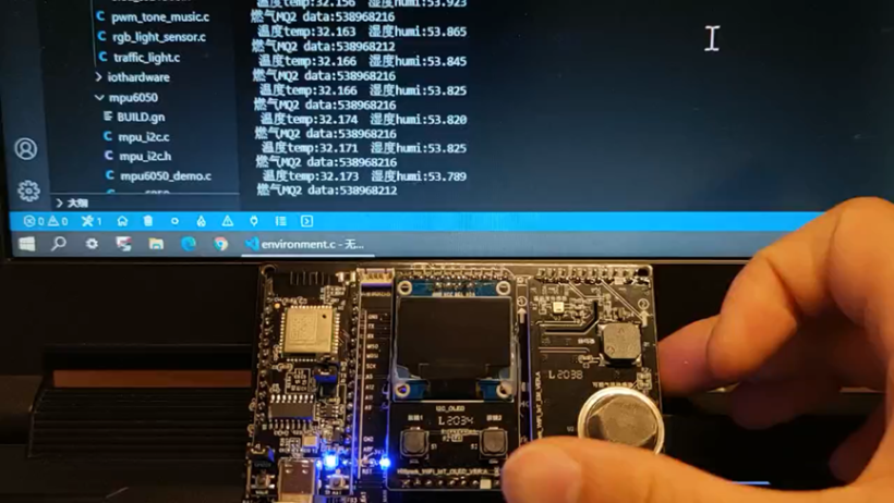
可以用手触摸或者对着温湿度传感器哈气,可以看到数值在变化,燃气传感器会微微发热,也有数值,条件允许可以点一根蜡烛,然后熄灭它,刚熄灭后的的白烟可以让MQ2传感器的数值发生变化。至此该实验全部结束。
3、SPI通信
(1)SPI函数接口
SPI相关理论可以参考Analoge Dialogue SPI。hi3861支持2路SPI。这里给出相关函数,具体实践可根据需求调用API即可。i2S相关定义在文件src\device\hisilicon\hispark_pegasus\sdk_liteos\include\hi_spi.h中。
// 初始化spi
hi_u32 hi_spi_init(hi_spi_idx spi_id, hi_spi_cfg_init_param init_param, const hi_spi_cfg_basic_info *param);
// 中断模式配置
hi_u32 hi_spi_set_irq_mode(hi_spi_idx id, hi_bool irq_en);
// dma模式配置
hi_u32 hi_spi_set_dma_mode(hi_spi_idx id, hi_bool dma_en);
// 从机写
hi_u32 hi_spi_slave_write(hi_spi_idx spi_id, hi_pvoid write_data, hi_u32 byte_len, hi_u32 time_out_ms);
// 从机度
hi_u32 hi_spi_slave_read(hi_spi_idx spi_id, hi_pvoid read_data, hi_u32 byte_len, hi_u32 time_out_ms);
// 主机写
hi_u32 hi_spi_host_write(hi_spi_idx spi_id, hi_pvoid write_data, hi_u32 byte_len);
// 主机读
hi_u32 hi_spi_host_read(hi_spi_idx spi_id, hi_pvoid read_data, hi_u32 byte_len);
4、I2S通信
(1)I2S函数接口
I2S相关理论可以参考Analoge Dialogue I2S。hi3861支持一路I2S。这里给出相关函数,具体实践可根据需求调用API即可。i2S相关定义在文件src\device\hisilicon\hispark_pegasus\sdk_liteos\include\hi_i2s.h中。
/**
* @ingroup iot_i2s
*
* sample rate.
*/
typedef enum {
    HI_I2S_SAMPLE_RATE_8K = 8,
    HI_I2S_SAMPLE_RATE_16K = 16,
    HI_I2S_SAMPLE_RATE_32K = 32,
    HI_I2S_SAMPLE_RATE_48K = 48,
} hi_i2s_sample_rate;

/**
* @ingroup iot_i2s
*
* resolution.
*/
typedef enum {
    HI_I2S_RESOLUTION_16BIT = 16,
    HI_I2S_RESOLUTION_24BIT = 24,
} hi_i2s_resolution;

/**
* @ingroup iot_i2s
*
* I2S attributes.
*/
typedef struct {
    hi_i2s_sample_rate sample_rate;  /**< i2s sample rate, type hi_i2s_sample_rate.CNcomment:采样率,类型为
                                          hi_i2s_sample_rate。CNend */
    hi_i2s_resolution resolution;   /**< i2s resolution, type hi_i2s_resolution.CNcomment:解析度,类型为
                                          hi_i2s_resolution。CNend */
} hi_i2s_attribute;
hi_u32 hi_i2s_init(const hi_i2s_attribute *i2s_attribute);
hi_u32 hi_i2s_read(hi_u8 *rd_data, hi_u32 rd_len, hi_u32 time_out_ms);
hi_u32 hi_i2s_write(hi_u8 *wr_data, hi_u32 wr_len, hi_u32 time_out_ms);
文章相关附件可以点击下面的原文链接前往下载
https://ost.51cto.com/resource/2684。
Recommend
About Joyk
Aggregate valuable and interesting links.
Joyk means Joy of geeK