

Let there be light!
source link: https://twiddlingbits.net/artificial-sun
Go to the source link to view the article. You can view the picture content, updated content and better typesetting reading experience. If the link is broken, please click the button below to view the snapshot at that time.

There is something fascinating about observing a miniature world, be it swimming in an aquarium, simulated on a screen, or planted in a terrarium. With this in mind, I decided to build a terrarium with an immersive twist: a programmable set of LEDs whose brightness and color mimic that of the sun.
Let's explore the hardware, software, and terrarium setup that bring this world to life! 🌍
The hardware
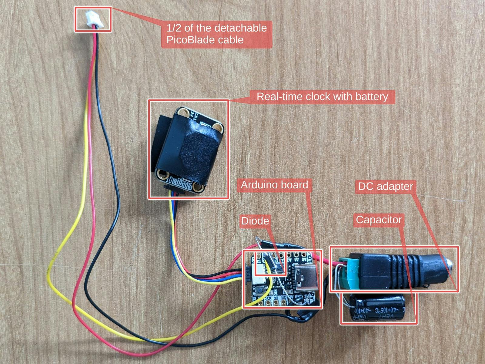
This project uses several hardware components:
An Arduino board capable of running CircuitPython (Adafruit QT Py RP2040)
A compatible real-time clock (Adafruit PCF8523)
- This will also require an appropriate battery
A means of connecting them (STEMMA QT cable)
A means of connecting that to the Arduino board
- I wanted a way to detach the LED ring from the rest of the assembly so I used a pair of matching Molex PicoBlade-compatible 3-pin cables (such as these)
An external power supply for the LEDs
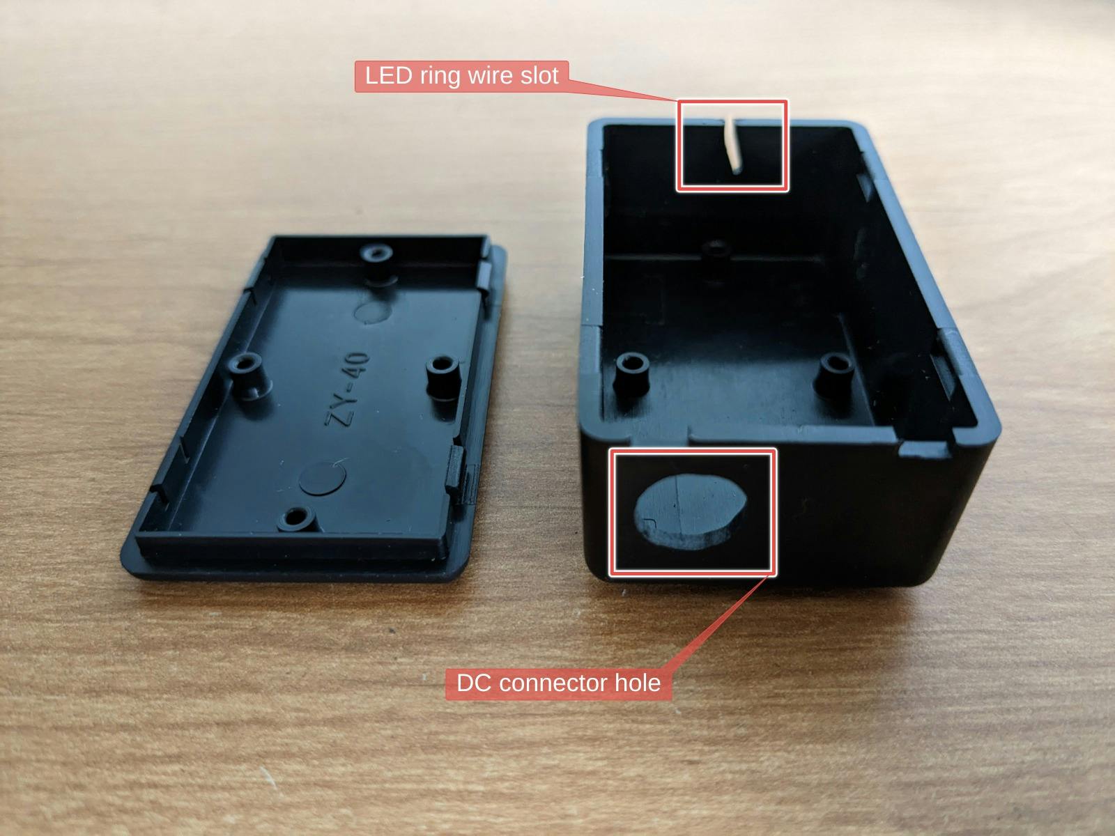
A "project box" capable of holding these components
I power both the LED ring and Arduino board via a 5V 2A power supply with a DC power adapter. This requires additional components:
- A 1000 µF capacitor used across the + and - terminals of the DC adapter, as noted here:
When using a DC power supply, or an especially large battery, we recommend adding a large capacitor (100 to 1000 µF, 6.3V or higher) across the + and – terminals.
- A diode (such as the common 1N4007 rectifier diode) between the 5V pin on your board and the power supply, as noted here:
5V - This is 5v out from the USB port. You can also use this as a voltage input but you must have some sort of diode (schottky, signal, power, really anything) between your external power source and this pin with anode to battery, cathode to 5V pin.
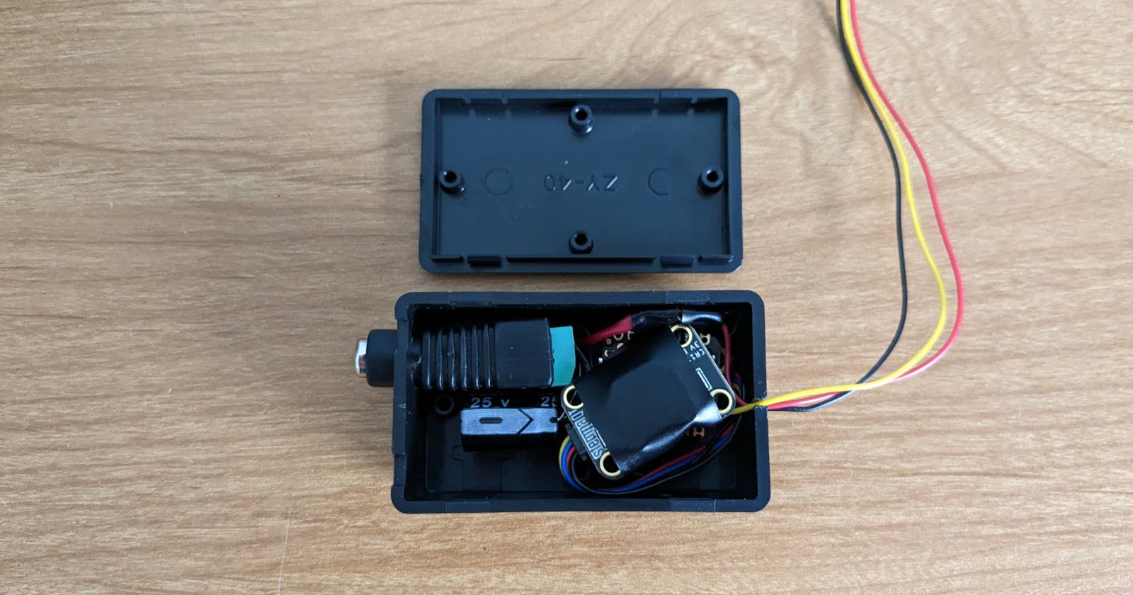
Solder the LED ring input (labeled "DIN" or "DI") to the digital pin 5 (labeled "SCL") on your board, and run the power and ground wires to their appropriate DC adapter terminals. Power the Arduino board with a wire to ground and the diode mentioned above. Make sure the capacitor is connected as required. Lastly, hook up the real-time clock using the STEMMA QT cable. My finished assembly looks like this:
To prepare the project box, I drilled out a hole for the female DC connector and sawed a slot on the opposite side for the LED ring wires:
Fit the assembly into the project box:
The software
This process assumes use of a Linux system and basic experience working with Arduino boards and the command line.
The software controlling the artificial sun is written in CircuitPython. Follow this guide to set it up on a QT Py RP2040 board.
Make sure you install the library bundle, then obtain the source code:
git clone https://github.com/jcrd/artificial-sun
Assuming the name of your device is CIRCUITPY, you can use an included update script to set the correct current time of your real-time clock and install the code file:
cd artificial-sun
./update.sh
Your sun should now be radiating light (and a little warmth for good measure 🌞).
How does it work?
The main logic of the code is in the linear interpolation of a small set of data relating time-of-day to LED light brightness and color.
light_data = [
    # Time, (Brightness, (Red, Green, Blue, White color))
    (0.0, (0.0, (0, 0, 0, 0))),
    (7.0, (0.1, (244, 254, 169, 0))),
    (8.0, (0.2, (243, 254, 174, 0))),
    (13.0, (1.0, (234, 254, 202, 0))),
    (18.0, (0.2, (243, 254, 174, 0))),
    (19.0, (0.1, (244, 254, 169, 0))),
    (24.0, (0.0, (0, 0, 0, 0))),
]
Its meant to be an approximation of sunrise, midday, and sunset. I expect the data to change as I continue experimenting with it over time.
The lerp function itself is straightforward:
def lerp(begin, end, t):
    return begin + t * (end - begin)
It calculates a position between the begin and end values given a percentage t. For example: let's start at 0 and end at 20; a t value of 0.4 is the value 8.
This function is used to interpolate between the brightness and color values associated with each time-of-day set:
def get_light_lerp(daytime):
    pt, (pb, pc) = (0, (0, (0, 0, 0, 0)))

    for t, (b, c) in light_data:
        if t == daytime:
            print("{}: {} @ {}".format(t, c, b))
            return (b, c)
        if t < daytime:
            pt, pb, pc = t, b, c
            continue
        lt = (daytime - pt) / (t - pt)
        lb = lerp(pb, b, lt)
        lc = tuple(int(lerp(pc[i], v, lt)) for i, v in enumerate(c))
        print("{} -> {} ({}): {} @ {}".format(pt, t, lt, lc, lb))
        return (lb, lc)
Let's explore the logic imagining its 11 o'clock:
If the current time matches a set exactly, return the associated data.
Otherwise, loop through the data recording each set with a time less than 11.
When a time greater than 11 is encountered, the last recorded set will be the beginning of the lerp function, while the current set is the end.
- Given the above data, the beginning and end sets will be at 8 and 13 o'clock respectively.
With this, calculate the percentage that describes 11 o'clock:
(11−8)/(13−8)=0.6
- Now the brightness and color values can be individually interpolated between the two sets using the percentage! 🤯
The terrarium
The first step of building a terrarium is to select the enclosure itself. I used a generic pentagonal "geometric" terrarium, readily available online and in local hobby stores. The design of your enclosure will also determine if your terrarium is "open" or "closed":
An open terrarium allows air to circulate throughout, meaning moisture will evaporate;
A closed terrarium will have a lid of some sort (think: mason jar), meaning moisture will be sealed inside.
This critical difference determines the plants most suitable for your terrarium. I recommend you check out one of the many online guides that go into detail about which plants to select and the ideal makeup of your substrate. As my enclosure is open, I collected the appropriate substrate materials, picked out some succulents, and got to work assembling my world. 🌵
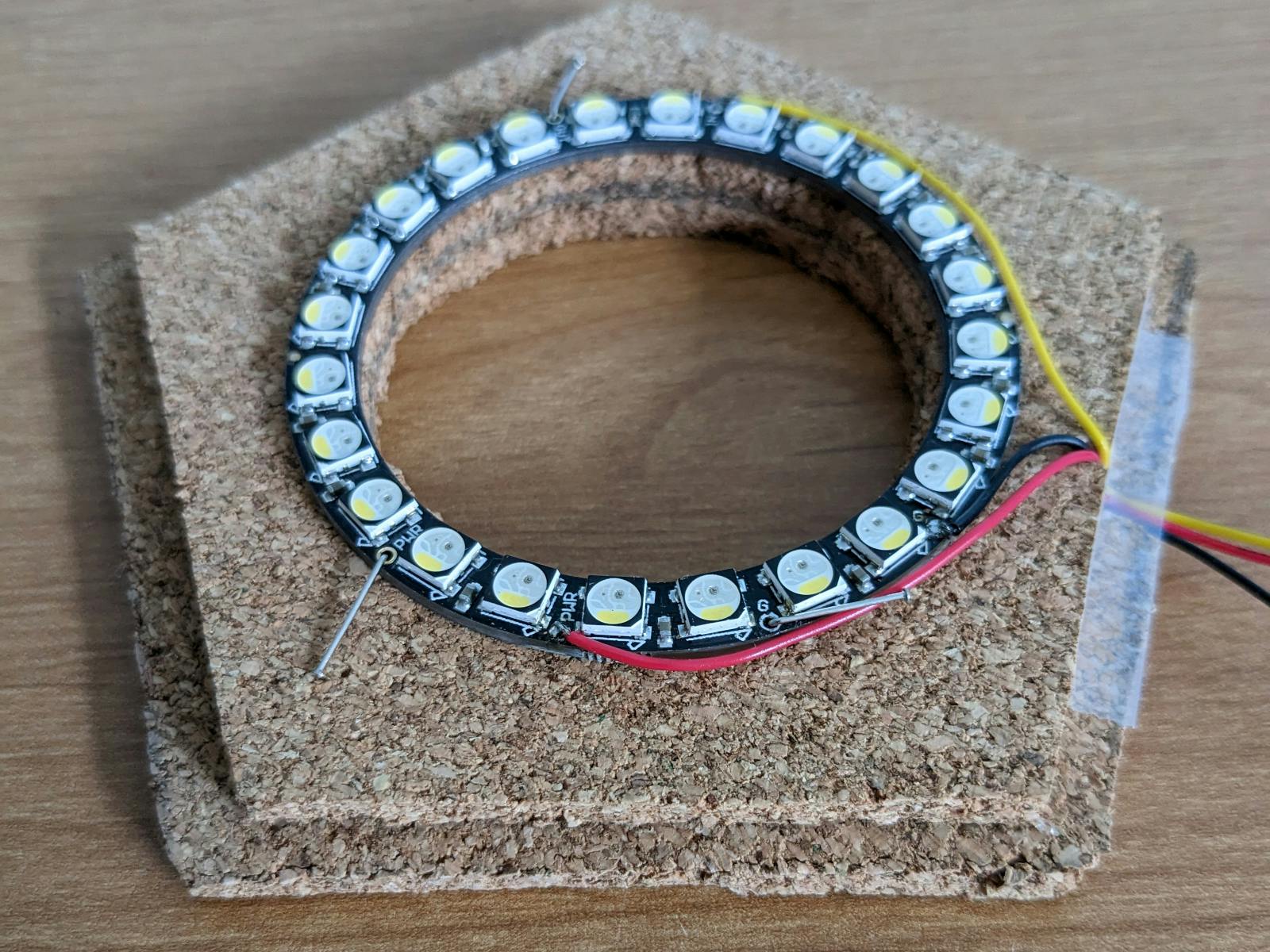
Next, it was time to give it light by attaching the LED ring. There are many ways to go about this. After some failed experimentation, I settled on using corkboard to construct a "lid" for the open face of my enclosure made of two layers glued together with a hole the size of the inner diameter of the LED ring cut out of each so that air is still able to circulate. This only required the use of scissors, a precision knife, and a hot glue gun. Finally, I pushed pins through the LED ring's PCB holes to fix it to the underside of the corkboard assembly so that it can be easily detached if necessary.
Here's the final product:
For more pizzazz, you might consider building something similar out of wood!
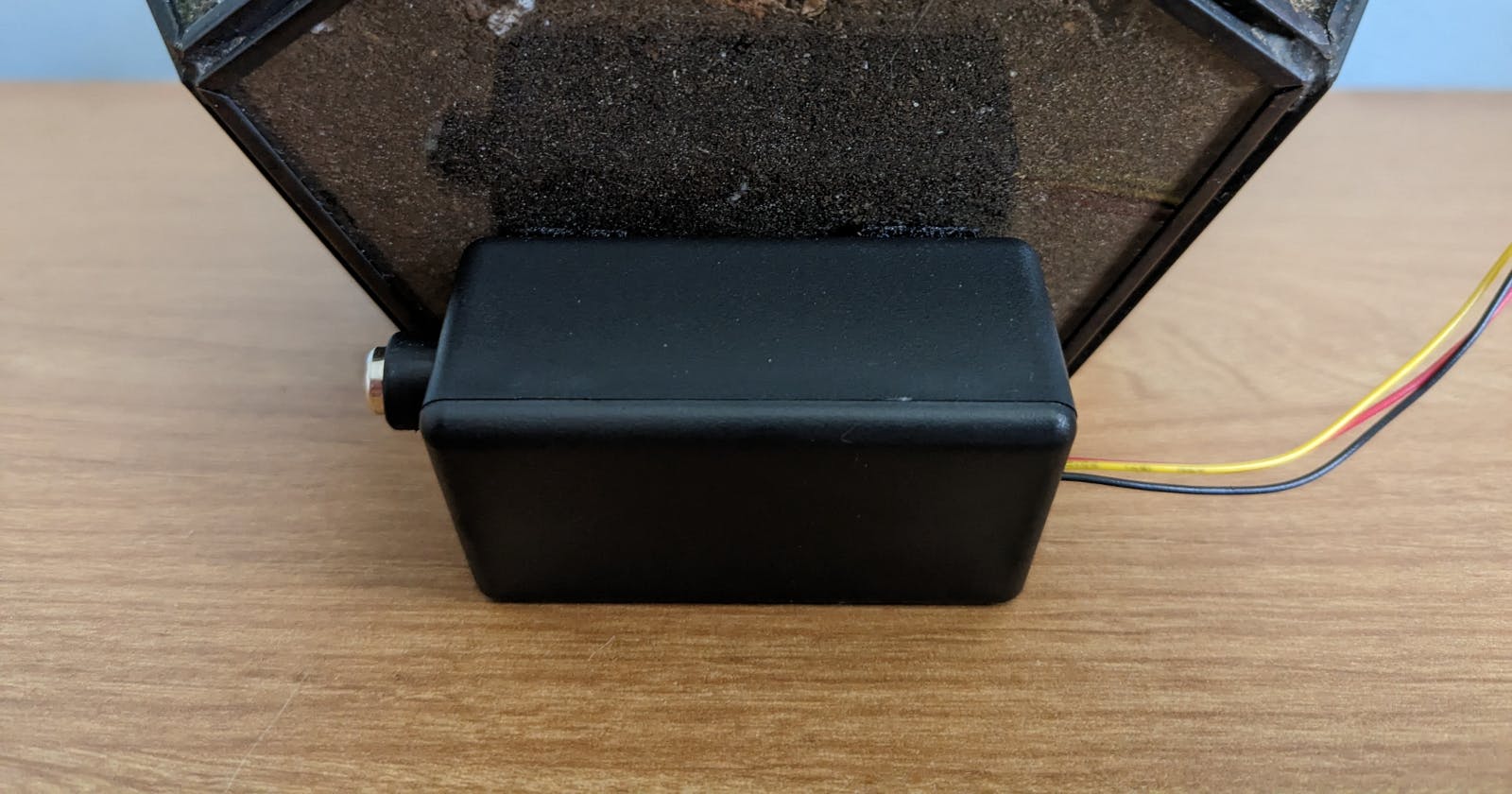
Finally, I cut a piece of adhesive hook and loop tape (commonly known by the brand name Velcro) to fit the project box which I attached to the back of the terrarium:
Supply power to the DC adapter and step back to revel in the miniature majesty!

Recommend
About Joyk
Aggregate valuable and interesting links.
Joyk means Joy of geeK