

Reverse-engineering an airspeed/Mach indicator from 1977
source link: http://www.righto.com/2023/01/reverse-engineering-airspeedmach.html
Go to the source link to view the article. You can view the picture content, updated content and better typesetting reading experience. If the link is broken, please click the button below to view the snapshot at that time.

Reverse-engineering an airspeed/Mach indicator from 1977
Reverse-engineering an airspeed/Mach indicator from 1977
How does a vintage airspeed indicator work? CuriousMarc picked one up for a project, but it didn't have any documentation, so I reverse-engineered it. This indicator was used in the cockpit panel for business jets such as the Gulfstream G-III, Cessna Citation, and Bombardier Challenger CL600. It was probably manufactured in 1977 based on the dates on its transistors.
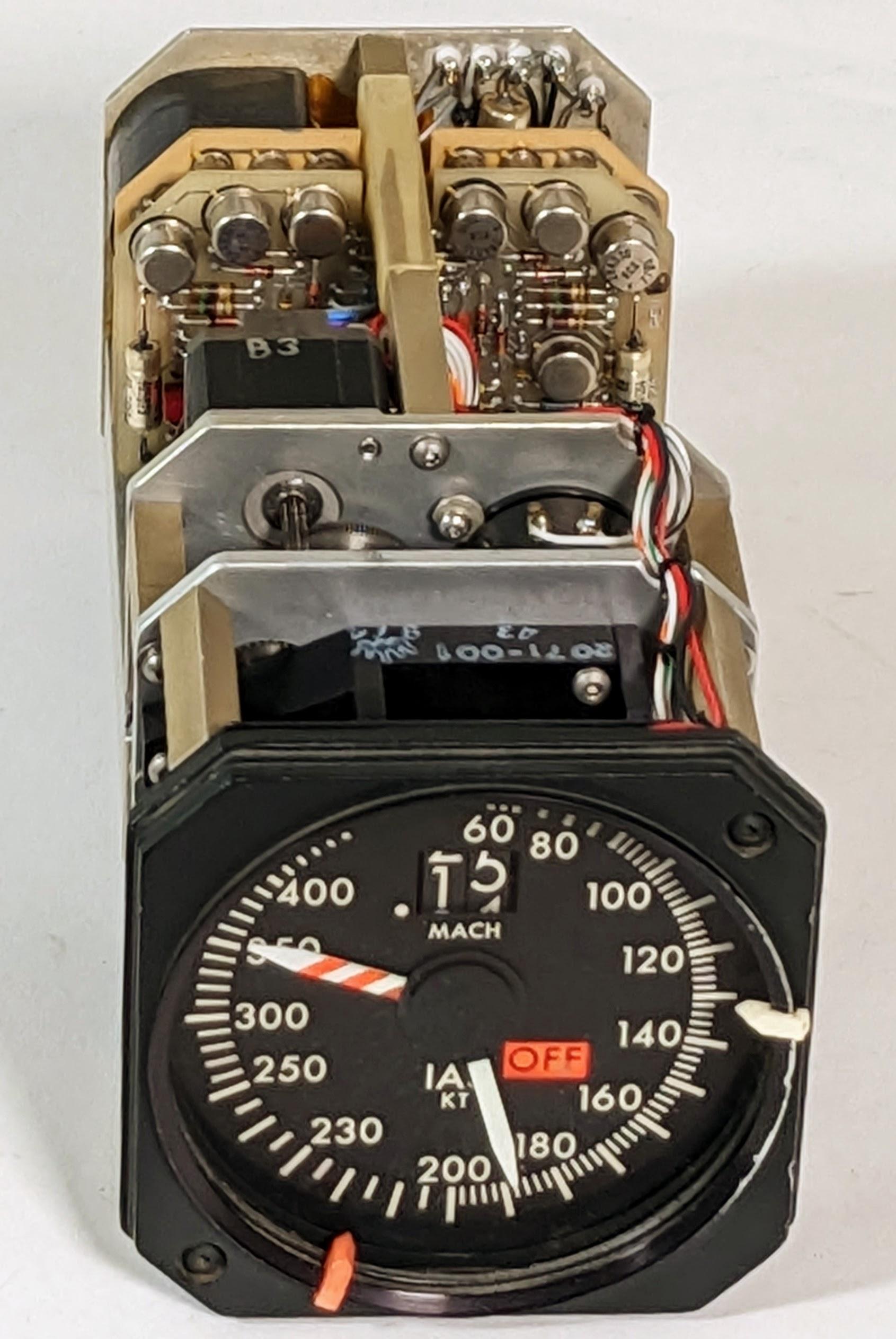
You might expect that the indicators on an aircraft control panel are simple dials. But behind this dial is a large, 2.8-pound box with a complex system of motors, gears, and feedback potentiometers, controlled by two boards of electronics. But for all this complexity, the indicator doesn't have any smarts: the pointers just indicate voltages fed into it from an air data computer. This is a quick blog post to summarize what I found.
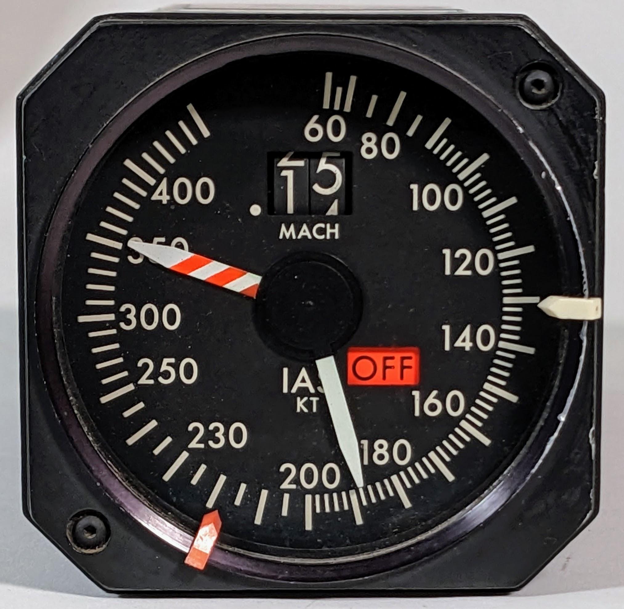
The dial has two rotating pointers: the white pointer indicates airspeed in knots while the striped pointer indicates the maximum airspeed (which varies depending on altitude). The "digital" indicator at the top shows Mach number from 0.10 to 0.99, implemented with rotating digit wheels. When the unit is operating, the OFF indicator flag switches to black. The flag switches to a bright VMO warning if the pilot exceeds the maximum airspeed.1 On the rim of the dial, two small markers called "bugs" can be manually moved to indicate critical speeds such as takeoff speed.
In use, the indicator is connected to a Sperry air data computer and receives voltage signals to control the dial positions.3 The air data computer measures the static and dynamic air pressure from pitot tubes and determines the airspeed, Mach number, altitude, and other parameters. (These calculations become nontrival near Mach 1 as air compresses and the fluid dynamics change.) Since we didn't have the air data computer or its specifications, I needed to figure out the connections from the computer to the display.
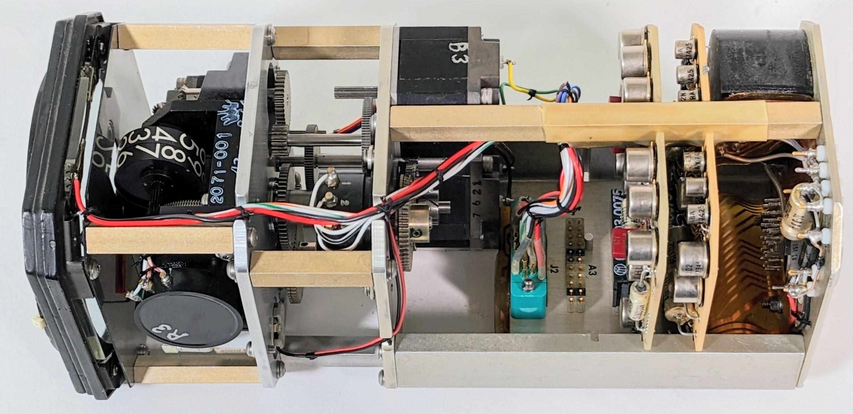
With the unit's cover removed, you can see the internal mechanisms and circuitry. Each of the three indicators is controlled by a small DC motor with a potentiometer providing feedback. To the right, two circuit boards provide the electronics to drive the indicators.4 At the upper right, the black blob is a 26-volt 400-Hertz transformer to power the unit. Some power supply components are in front of it. Below the transformer is an orangish flexible printed-circuit board, which seems advanced for the timeframe. This flexible ribbon connects the transformer, the external connector, and the printed-circuit board sockets, providing the backplane for the system.
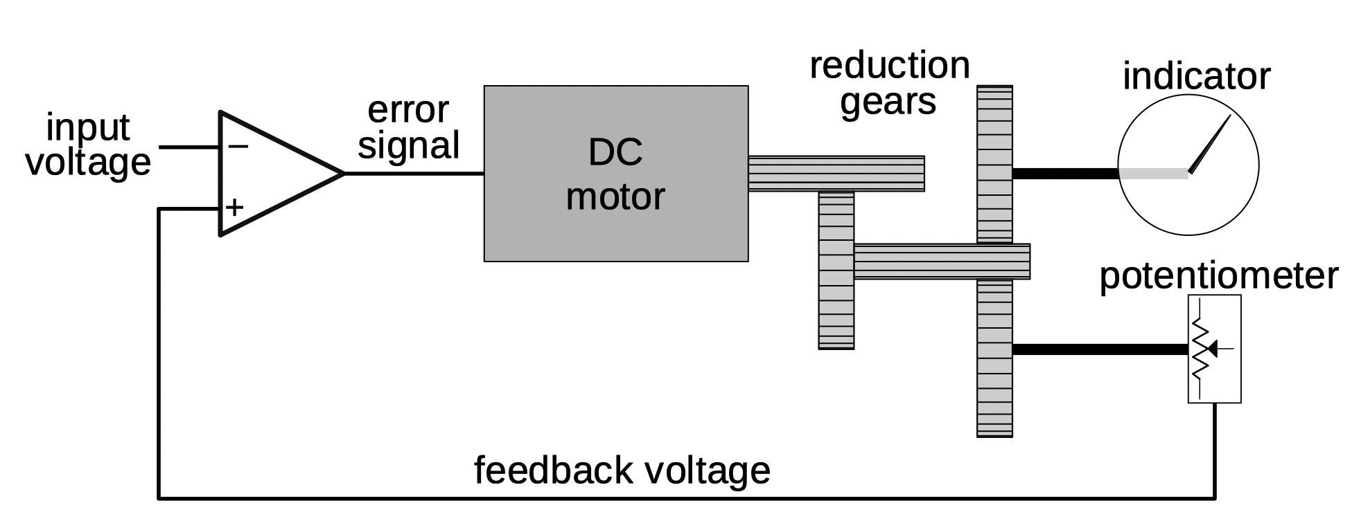
The diagram below shows the principle behind the servo mechanism that controls each indicator. The goal is to rotate the indicator to a position corresponding to the input voltage. A feedback loop is used to achieve this. The potentiometer provides a voltage proportional to its rotation. The input voltage and the feedback voltage are inputs to an op amp, which generates an error signal based on the difference between the inputs. The error signal rotates the DC motor in the appropriate direction until the potentiometer voltage matches the input voltage. Because the indicator and the potentiometer are geared together, the indicator will be in the correct position. As the input voltage changes, the system will continuously track the changes and keep the indicator updated.
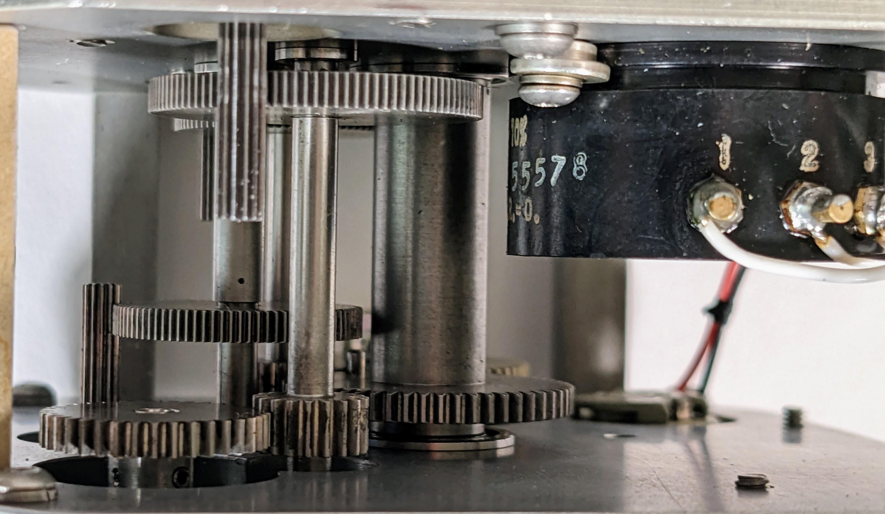
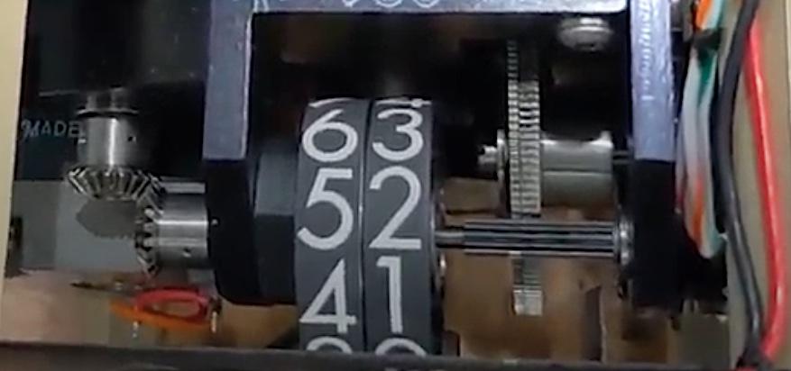
Because the DC motor spins much faster than the dial moves, reduction gears slow the rotation. The photo below shows the gear train in the unit. A potentiometer is at the upper-right with three wires attached.
The Mach number has additional gearing to rotate the numbered wheels. When the low-digit wheel cycles around, it advances the high-digit wheel, similar to an odometer.
Fault checking
One interesting feature of the indicator unit is that it implements fault checking to alert the pilot if something goes wrong. The front panel has a three-position flag. By default it's in the OFF position. Powering the coil in one direction rotates the flag to the blank side. Powering the coil in the other direction rotates the flag to the "VMO" position which indicates that the pilot has exceeded the maximum operating speed.
I figured that powering up the unit would move the flag out of the OFF position, but it's more complicated than that. First, the unit checks that the air data computer is providing a suitable reference voltage. Second, the unit verifies that the motor voltages for the two needles are within limits; this ensures that the servo loop is operating successfully. Third, the unit checks that signals are received on status pins K and L. The unit only moves out of the OFF state if all these conditions are satisfied.5 Thus, if the unit receives bad signals or is malfunctioning, the pilot will be alerted by the OFF indicator, rather than trusting the faulty display.
The circuitry
The unit is powered by 26 volts, 400 Hz, a standard voltage for aviation. A small transformer provides multiple outputs for the various internal voltages. The unit has four power supplies: three on the first board and one on the back wall of the unit. One power supply is for the status indicator, one is for the op amps, one powers the 41.7V motors, and the fourth provides other power.
One subtlety is how the feedback potentiometers are powered. The servo loop compares the potentiometer voltage with the input voltage. But this only works if the potentiometer and the input voltage are using the same reference. One solution would be for the indicator unit and the air data computer to contain matching precision voltage regulators.[reference] Instead, the system uses a simpler, more reliable approach: the air data computer provides a reference voltage that the indicator unit uses to power the potentiometers.6 With this approach, the air data computer's voltage reference can fluctuate and the indicator will still reach the right position. (In other words, a 5V input with a 10V reference and a 6V input with a 12V reference are both 50%.)
The diagram below shows the board with the servo circuitry. The board uses dual op-amp integrated circuits, packaged in 10-pin metal cans that protected against interference.7 The ICs and some of the other components have obscure military part numbers; I don't know if this unit was built for military use or if military-grade parts were used for reliability.
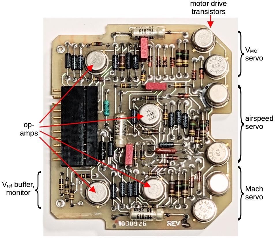
The circuitry in the lower-left corner handles the reference voltage from the air data computer. The board buffers this voltage with an op amp to power the three feedback potentiometers. The op amp also ensures that the reference voltage is at least 10 volts. If not, the indicator unit shows the "OFF" flag to alert the pilot.
The schematic below shows one of the servo circuits; the three circuits are roughly the same. The heart of the circuit is the error op amp in the center. It compares the voltage from the potentiometer with the input voltage and generates an error output that moves the motor appropriately. A positive error output will turn on the upper transistor, driving the motor with a positive voltage. Conversely, a negative error output will turn on the lower transistor, driving the motor with a negative voltage. The motor drive circuit has clamp diodes to limit the transistor base voltages.

The op amp also receives a feedback signal from the motor output. I don't entirely understand this signal, which goes through a filter circuit with resistors, diodes, and a capacitor. I think it dampens the motor signal so the motor doesn't overshoot the desired position. I think it also keeps the transistor drive signal biased relative to the emitter voltage (i.e. the motor output).
On the input side, the potentiometer voltage goes through an op amp follower buffer, which simply outputs its input voltage. This may seem pointless, but the op amp provides a high-impedance input so the potentiometer's voltage doesn't get distorted.
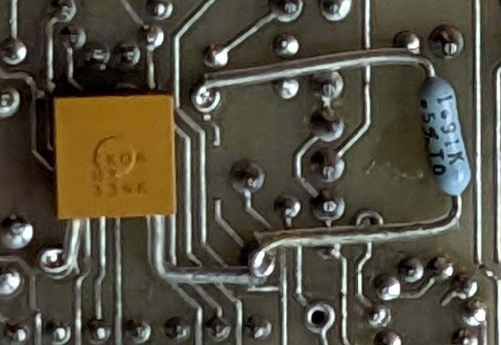
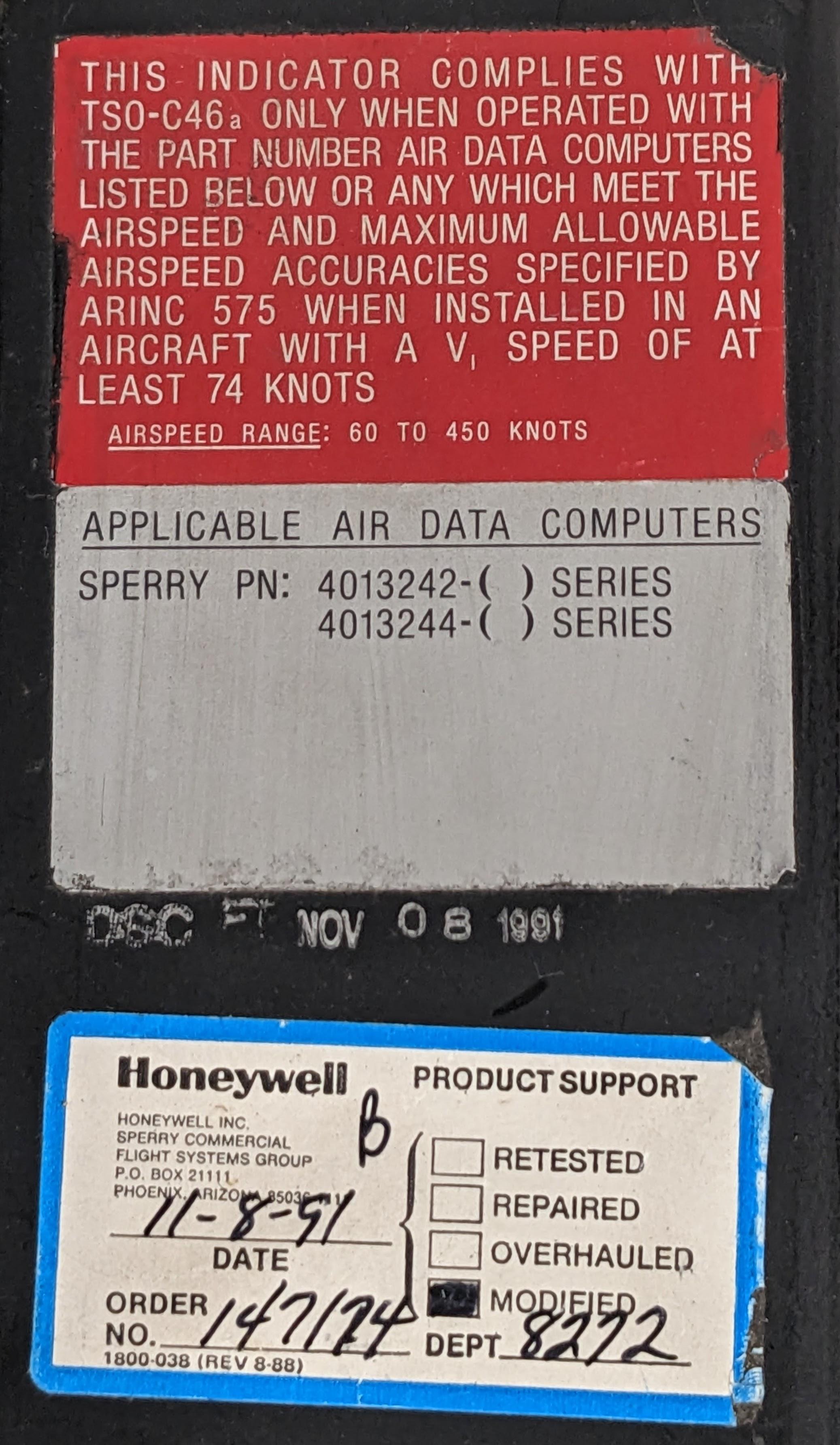
The external input voltage goes through a resistor/capacitor circuit to scale it and filter out noise. Curiously, the circuit board was modified by cutting a trace and adding a resistor and capacitor to change the input circuit for one of the inputs. In the photo below, you can see the added resistor and capacitor; the cut trace is just to the right of the capacitor. I don't know if this modification changed the scale factor or if it filtered out noise. A label on the box says that Honeywell performed a modification on November 8, 1991, which presumably was this circuit.
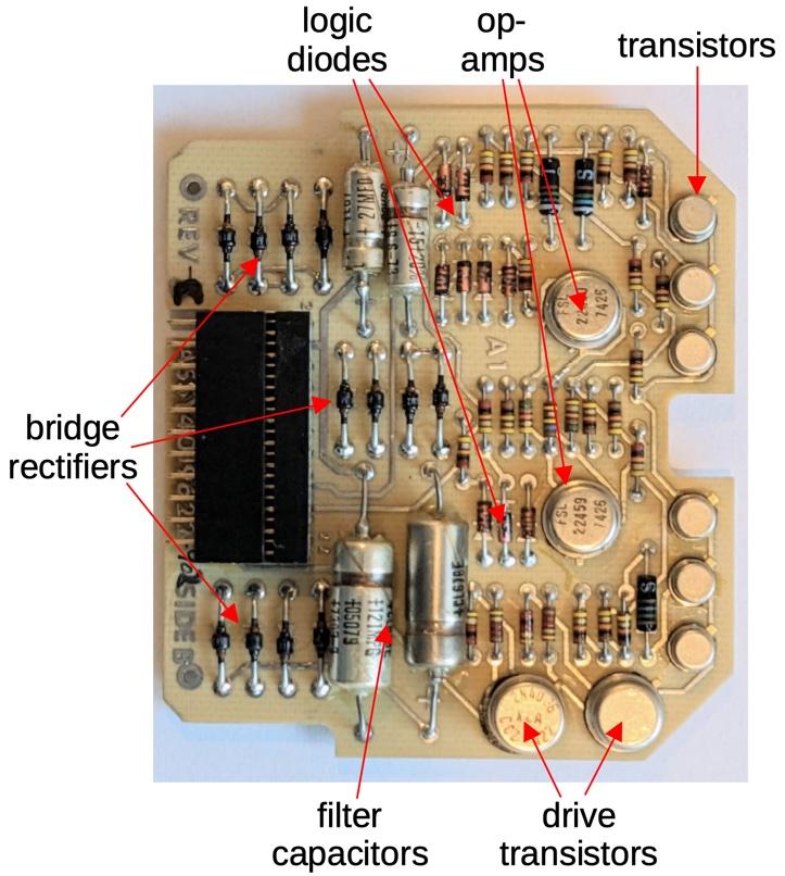
The second board implements three power supplies as well as the circuitry for the OFF/VMO flag. The power supplies are simple and unregulated, just diode bridges to convert AC to DC, along with filter capacitors. Most of the circuitry on the board controls the status flag. Two dual op amps check the motor voltages against upper and lower limits to ensure that the motors are tracking the inputs. These outputs, along with other logic status signals, are combined with diode-transistor logic to determine the flag status. Driver transistors provide +18 or -18 volts to the flag's coil to drive it to the desired position.
Conclusions
After reverse-engineering the pinout, I connected the airspeed indicator to a stack of power supplies and succeeded in getting the indicators to operate (video). This unit is much more complex than I expected for a simple display, with servoed motors controlled by two boards of electronics. Air safety regulations probably account for much of the complexity, ensuring that the display provides the pilot with accurate information. For all that complexity, the unit is essentially a voltmeter, indicating three voltages on its display. This airspeed indicator is a bit different from most of the hardware I examine, but hopefully you found this look at its internal circuitry interesting.
You can follow me on Twitter @kenshirriff or rss. I've also started experimenting with mastodon recently as @oldbytes.space@kenshirriff.
Notes and references
-
Since the unit has airspeed and maximum airspeed indicators, you might expect it to display the maximum airspeed warning flag based on the two speed inputs. Instead, the flag is controlled by input pin "L". In other words, the air data computer, not the indicator unit, determines when the maximum airspeed is exceeded. ↩
-
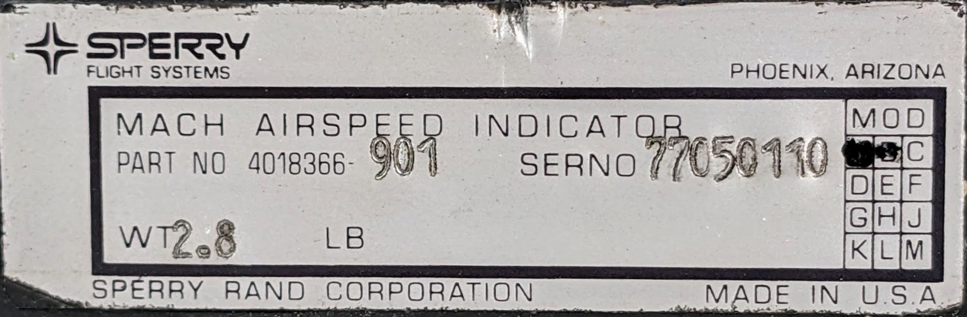
This unit is a "Mach Airspeed Indicator", 4018366, apparently also called the SI-225,2
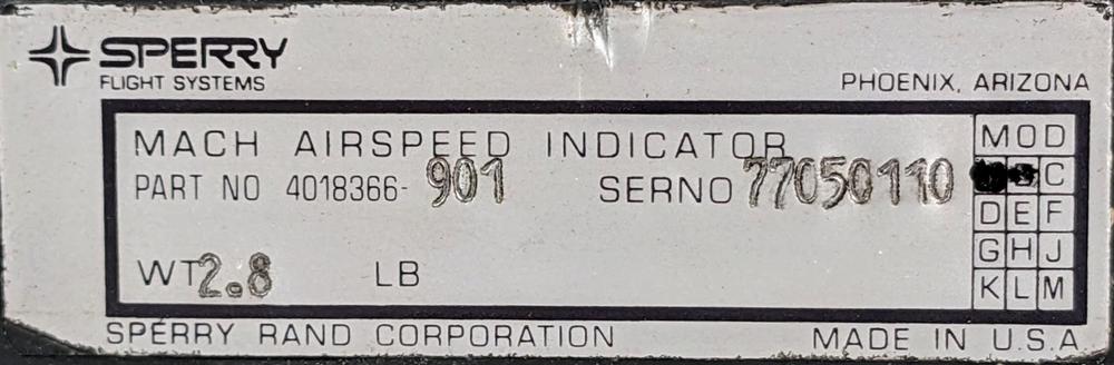 Product label with part number 4018366-901.
Note that the label says Sperry. In 1986, Sperry attempted to buy Honeywell but instead Burroughs made a hostile takeover bid. The merger of Sperry and Burroughs formed Unisys. A couple of months after the merger, the Sperry Aerospace Group was sold to Honeywell for $1.025 billion. Thus, the indicator became a Honeywell product. This corporate history explains why the unit has a Honeywell product support sticker.
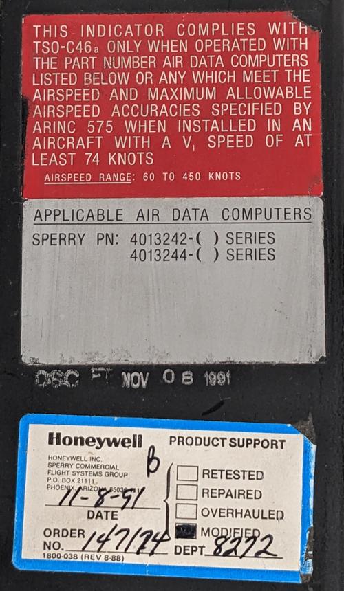 Labels on top of the unit indicate that it worked with the Sperry 4013242 and 4013244 air data computers. These became the Honeywell AZ-242 and AZ-244.
 -
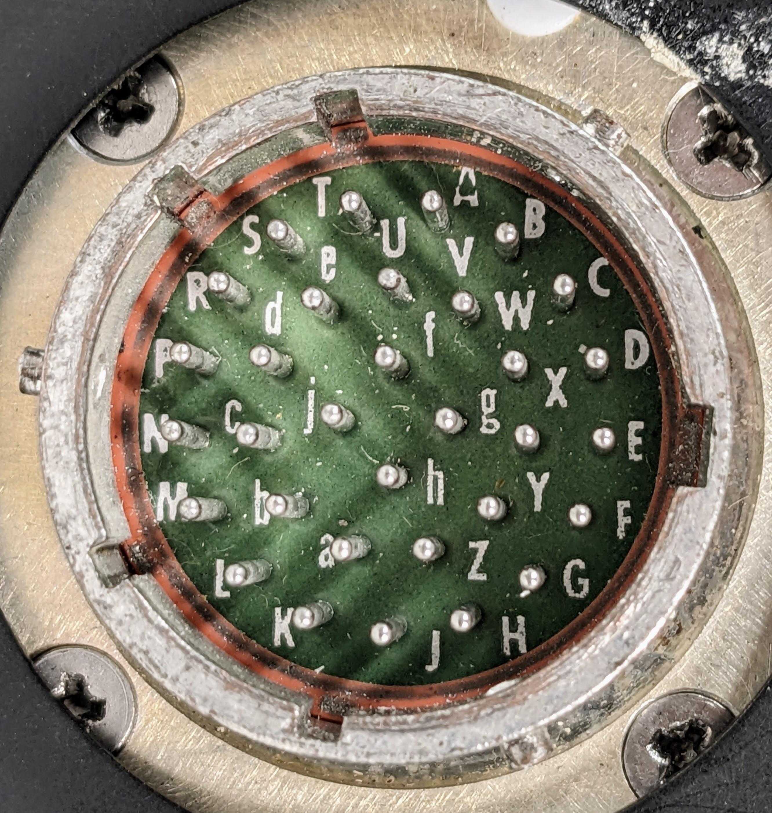
The connector is a 32-pin MIL Spec round connector. Most of the 32 pins are unused. The connector has complex keying with 5 slots. I assume the keying is specific to this indicator, so the wrong indicator doesn't get connected.
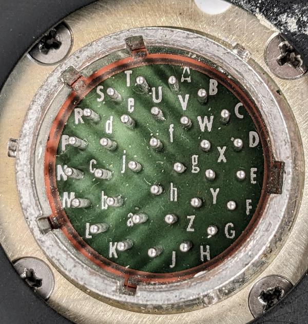 A closeup of the 32-pin connector, probably a MIL Spec 18-32.
For reference, here is the pinout of the unit. Since this is based on reverse engineering, I don't guarantee it 100%. Don't use this for flight!
GroundPin Use A 5V illumination B 5V illumination C Ground D E 26V 400 Hz F 26V 400 Hz G TBD H TBD J TBD K Enable L Speed ok M Signal ground N Ref. voltage P Vmax control voltage R Airspeed control voltage S Mach control voltage V Ground Pins U, W, X, Y, Z, a, b, c, d, e, f, g, h, and j are unused. ↩
-
The chassis has an empty slot for a third circuit board. My guess is that this chassis was used for multiple types of indicators and others required a third board. ↩
-
If the L pin goes low, the indicator will move to the VMO position. ↩
-
My hypothesis is that the correct reference voltage is 11.7 volts. This yields a scale factor of 1 volt equals 50 knots. It also matches up the display's change in scale at 250 knots with the measured scale change. ↩
-
The meter uses three different integrated circuits in 10-pin metal cans with mysterious military markings: "FHL 24988", "JM38510/10102BIC 27014", and "SL14040". These appear to all be equivalent to uA747 dual op amps. (Note that JM38510 is not a part number; it is a general military specification for integrated circuits. The number after it is the relevant part number.) ↩
Recommend
About Joyk
Aggregate valuable and interesting links.
Joyk means Joy of geeK