

Kenneth Finnegan: "One of my nice friends at Hurr…" - A Social Front O...
source link: https://social.afront.org/@kwf/109492743645650432
Go to the source link to view the article. You can view the picture content, updated content and better typesetting reading experience. If the link is broken, please click the button below to view the snapshot at that time.

Kenneth Finnegan: "One of my nice friends at Hurr…"
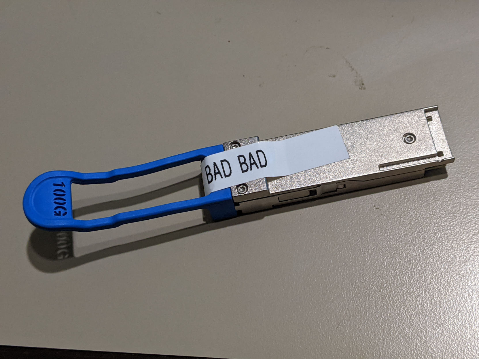

First comes off the ejection bail. I guess we're committed now since that was rather destructive.
Two tiny screws get us into the case. The grey putty stuff is thermal gap filler, which couples each part that puts off heat to the case for cooling.
Think of it like thermal paste, but it's designed to be thick and span a gap instead of just be a thin film.

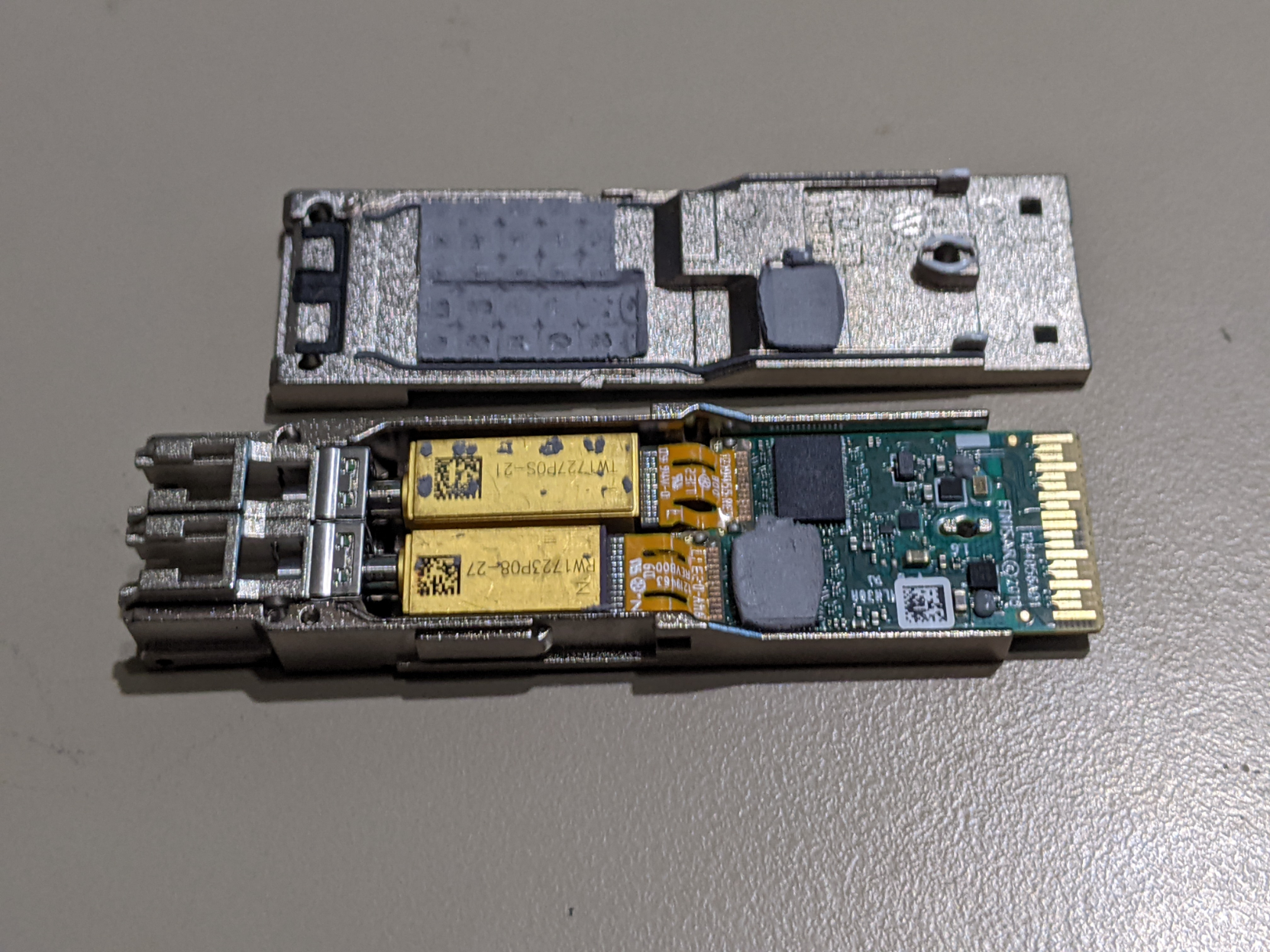

The TOSA and ROSA both need to handle four wavelengths of light moving 25Gbps each, so they're actually connected to the PCB with two layers of ribbon cables. One of the ribbons is just for the 4x25Gbps data channels, and the other is for power, biasing, etc, not high speed stuff to run the OSA parts.

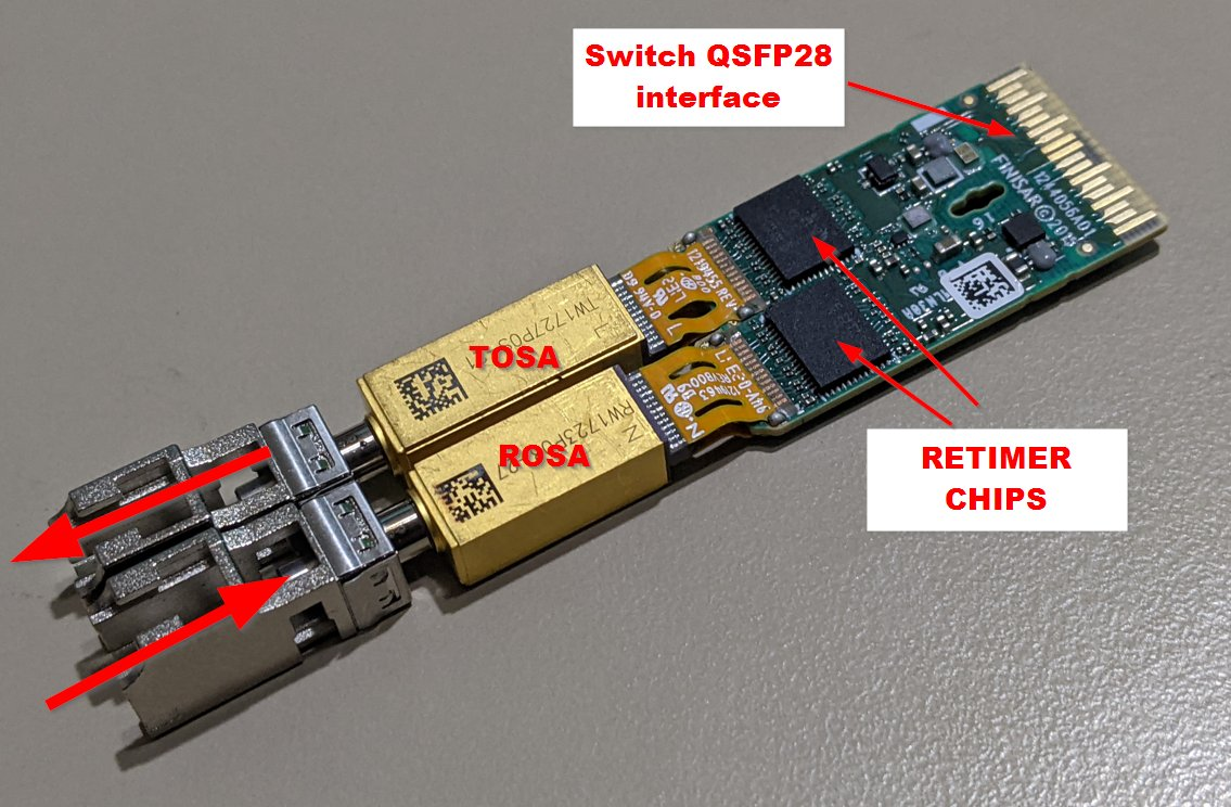
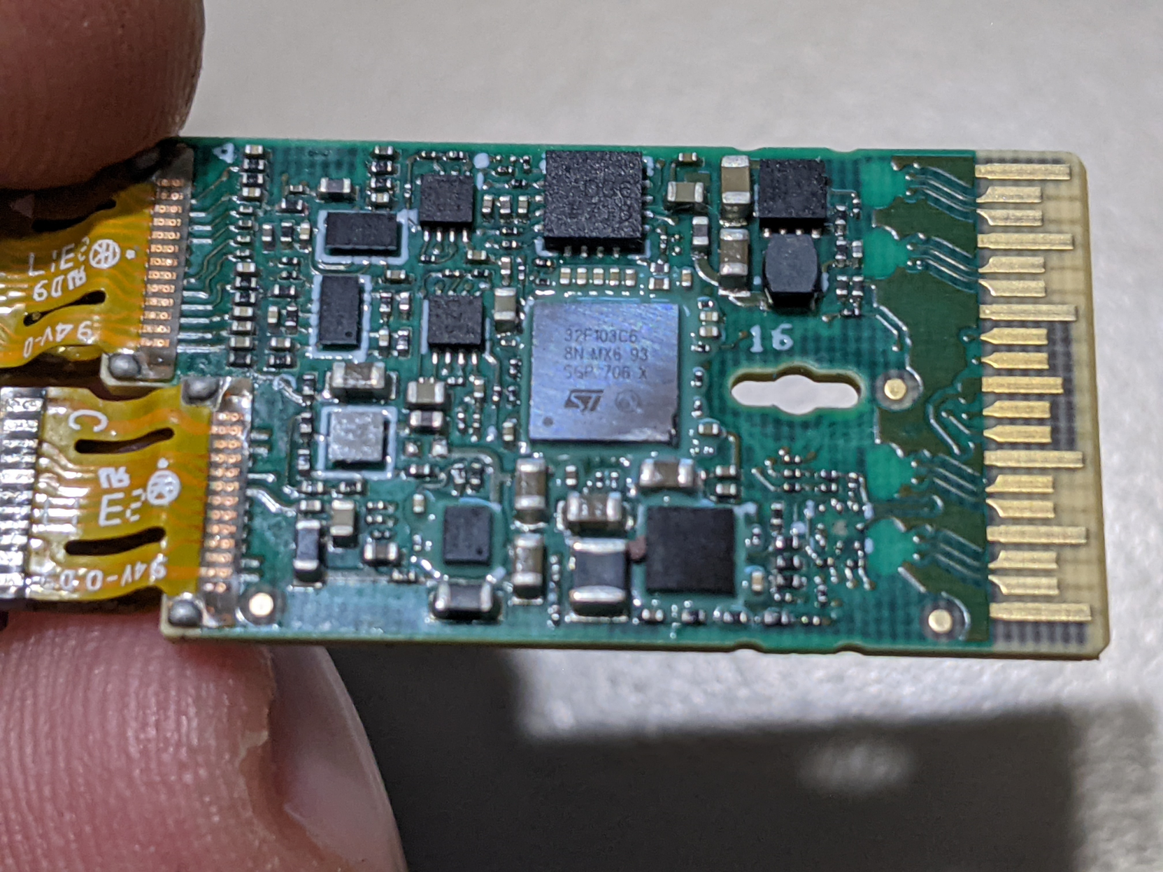
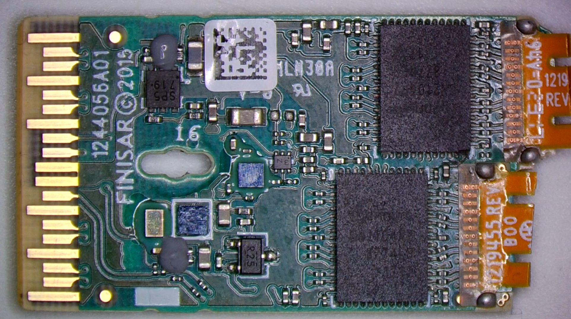
Looking on the other side of the whole assembly, the largest IC in the middle (the silver one) is the microcontroller that talks to the switch over an I2C bus to report telemetry and ID information, and pretty much everything else is voltage regulation for taking the 3.3V from the switch and regulating it down to lower voltages to drive the lasers.

And that microcontroller that runs the whole show is... a Cortex M3! An STM32F103C6 with 32kB of flash, 10kB of SRAM, and can run at up to 72MHz.
Meaning that this optic has more compute power than many early home computers.
You'll note that the ST microcontroller is silver, as are a few other ICs on this optic. This is actually a cost saving measure called "flip chip" packaging, where they don't waste the expense of the black plastic packaging and solder the silicon die straight down onto the board like it was a QFN. Absolutely wild.

While it's fun to think about malware on the ARM core in these, the data path is WAY faster than the Cortex M3 can handle. It's entirely an out-of-band manager of the electronics with no idea of what is going on in the Ethernet link itself.
That being said, some newer optics really DO have interactions in the data path. The most notable is the speed-changing optics which allow modern Ethernet switches (which only support 10G/25G/50G on their front panel ports) to still link up with a 1G Ethernet peer. The optic does the 10:1 speed change and implements clause 37 autoneg entirely inside the optic.
Granted, the firmware on optics actually *IS* field writable. I've coordinated with an optics vendor in the past to help a customer apply a firmware patch to 10,000 optics installed in Arista switches in the field by issuing the right magic sequence of write commands over the I2C bus from EOS.


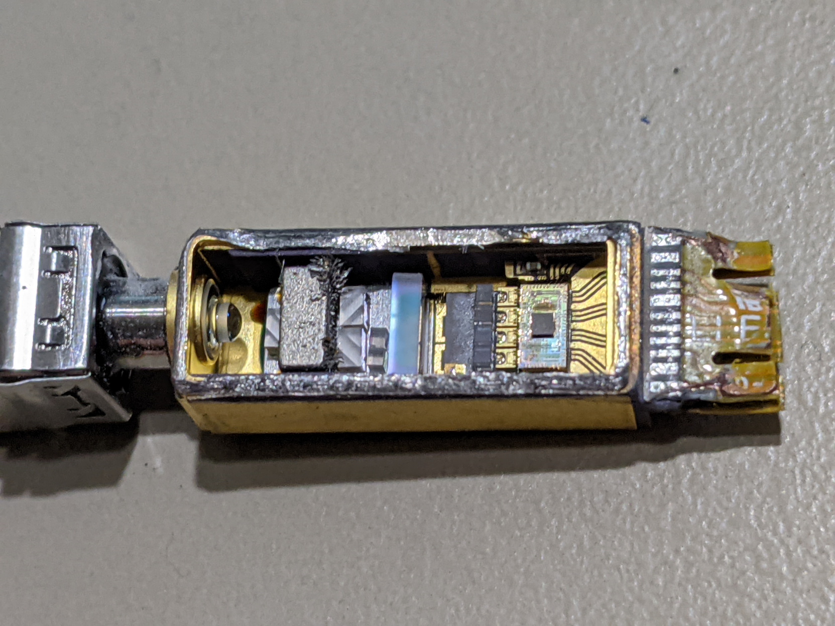

The keen eye will also notice that some of the Dremel debris from me cutting open the TOSA is... stuck to this cube and fuzzy... like it's magnetic...
And it it. That is a tiny magnet in the middle of the optical path, but why?
Physics talk. Remember that the transmitters here are lasers, which mean that the four lasers on the right are each their own resonant cavity, which leaks a fraction of the light to be useful. But if there was some kind of partial reflection out in the fiber somewhere, this could cause problems and destabilize these lasers, so we would like some way to let light OUT of the TOSA without letting any reflected light back into the lasers to cause problems, so we make an optical one-way valve...
MORE PHYSICS TALK: Light is a perpendicular E-M field, so if you used a vertical polarizer, and then passed the light through a magnetic field to rotate the polarization 45 degrees to line up with a //// diagonal polarizing filter on the other side of the magnet...
Think about the reverse path. //// polarizing filter, 45 degree rotation, horizontal light hitting a vertical polarizing filtering. BLOCKED.

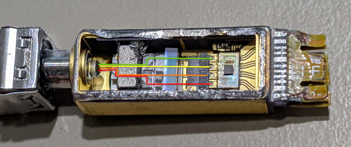
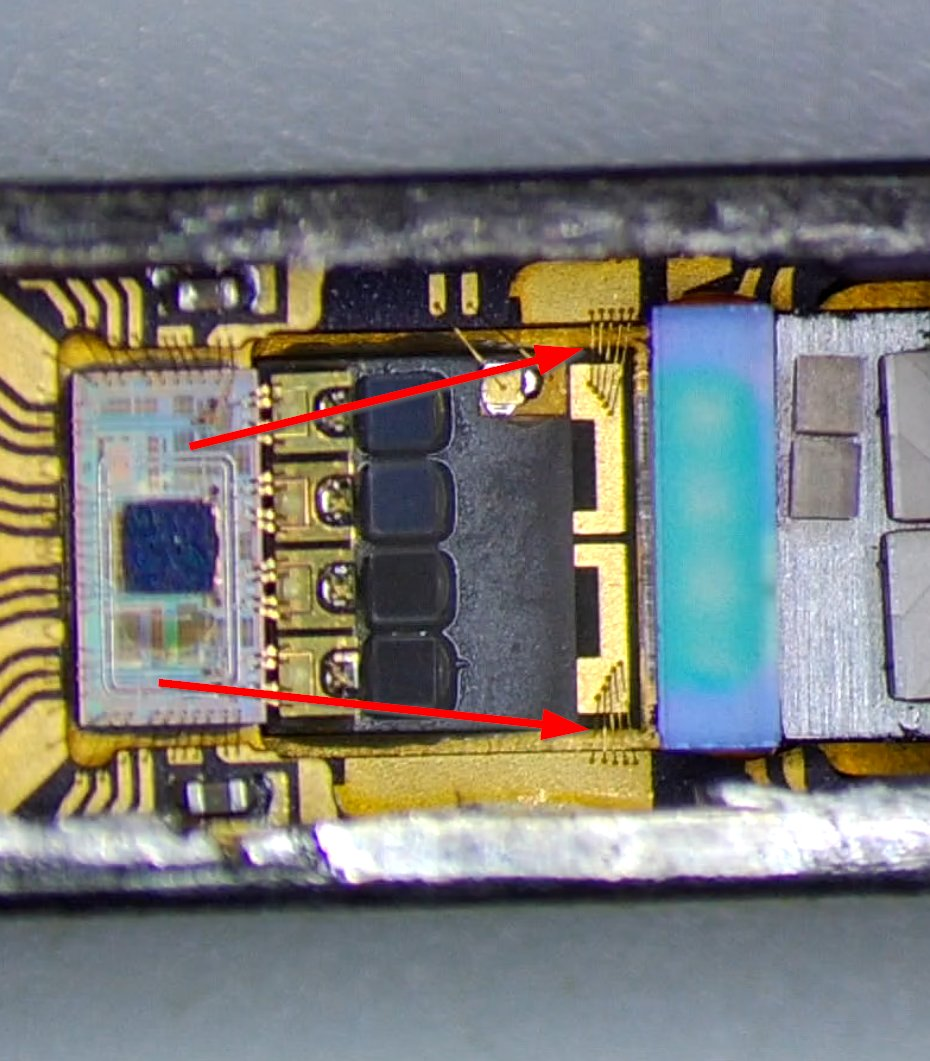
Putting the TOSA under my microscope, we can start to see some more of the finer details.
This is rotated from the last photos.
I'm not convinced whether the two missing lenses in the middle broke off before I got it, broke off while I was hacking my way into the package, or were just never there. A mystery for the ages.

For one thing, we see a tiny square and two bond wires landing on the platform holding the lasers and the first stage of the optics.
This is a silicon diode.
Fun diode fact: the junction voltage of a diode changes with temperature in a very predictable and consistent way, so it's very common for temperature sensors to measure the junction voltage of a diode or base of a transistor.

And a temperature sensor would imply some kind of temperature control, and this actually makes a lot of sense, because the four lasers are all different colors, but only SLIGHTLY different colors.
Each of the four lasers are only 4.5nm apart in wavelength, so the temperature really matters to keep them in their channel, so there's a peltier cooler underneath the platform holding the lasers and first optical stage so that the optic can electrically heat or cool the lasers to keep them at the right temperature!


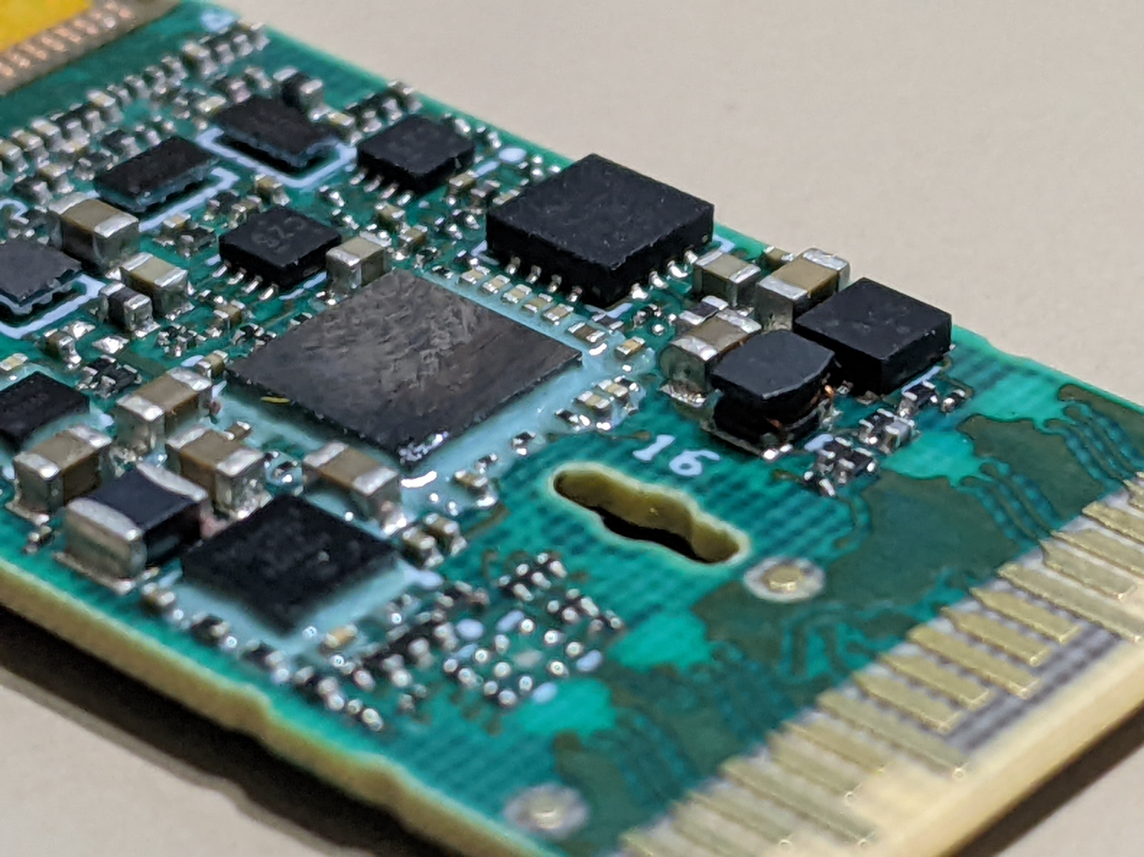
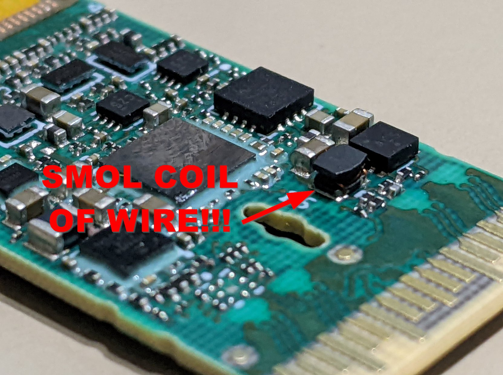
So lastly, here are some more photos of the PCB that runs from the QSFP edge connector to the ribbon cables attached to the ROSA and TOSA.  /fin
/fin
Thanks for reading. For those new here, I have a Liberapay which I'm using to fund the #MicroMirror project where I'm trying to fix Linux/free software distribution to users. https://liberapay.com/phirephly/

@kwf Is that grey rectangle on the left a magnet?
@ve7fim It is. You beat me to posting the explanation
@kwf nicely done! Had to zoom WAY in to tell those were prisms!
@kwf This stuff is MIND BLOWING. I recall your thread on birdsite a few years back when you tore down an earlier generation 100G optic that used TEN different wavelengths!
Seems the tech has moved forward; now we just need four!
@zorinlynx Well... NOW we only need one. 100G-LR is taking over the industry since it doesn't need the optical muxes anymore and just uses an electrical gearbox to combine the 20 PCS lanes from 4x25G to 1x100Gbps.
@kwf Of course this means there's probably an optic combining ten wavelengths at 100G each to put 1T on a single strand because that's how it rolls. :)
@zorinlynx Well... try 8x400Gbps, but you've got the right idea.
@PixelRefresh Fair. But really, I should just come with a warning in general.
@kwf That was awesome. I know very little about any of this, but it was fun to see how much goes into a fiber cable. Thanks for posting.
@kwf
Unbelievable integration scale. Thanks for the images and explanation!
@kwf thanks for bringing your optical disassemblies to mastodon!
@kwf Until this last comment, I didn't realize you were the same person as the one who gave this presentation:
https://www.youtube.com/watch?v=pltEYP_FnSA
(Thanks for the teardown. Very cool.)

@cstanhope Yep! That's me! I get around, when it comes to weird little nerdy parts of the Internet!
@kwf Although I did not understand all of it, this was fun to read. Very interesting as well. Thanks a lot!
@kwf I used these over 100m at a previous job, they were flawless. Nice to know how the sausage is made!
@kwf thanks for the breakdown & explanation, it was a fascinating to read.
@kwf Incredible thread; this is legit @foone level stuff and I am loving it!
I had no idea about the peltier cooler stuff, but it makes total sense! Do you know if that exists on more plebian 1G/10G optics? I have always been fascinated/concerned by how hot SFP modules get but it all seemed within spec. Now I am wondering if the heat is the optic trying to cool itself which might mean a bit of attention to airflow to keep them cooler might actually be beneficial.
@HMHackMaster @foone 1G/10G are a single color, so exact wavelength control is much less important for them.
@kwf Hmm, interesting how different the ROSA is to the TOSA. I would have thought that they would have identical optical pathways.
Am I right in guessing that the receivers are sensitive to very specific wavelengths, so it doesn't matter that the right beam hits the right detector, so it just scatters the entire beam over every detector?
@NeoFox The receivers are broadband, so you need very selective optical demux to break apart the signal. Either with a diffraction medium like a prism or often a diffraction grating based splitter.
@NeoFox @kwf I assume that’s why that last prism is so big? Presumably a cascade of prisms or something like thin film optics internally to pry those wavelengths apart? I mean if you think about how little say the red and yellow in white light diverge after going through a prism, and there’s about 150nm or 20% wavelength difference there - single digit nm deltas in 1000nm-ish light (<1%) must be pretty tricky to separate.
@kwf: Cooler! Wow! Now I need to learn how to use emoji on Mastodon. 
> a peltier cooler underneath the platform holding the lasers
Thanks, that was fun!
I really didn‘t expect the Peltier, now I am wondering in what other tiny parts they may be hidden and whether they can be a feature of the surface structure nowadays.
@kwf:Absolutely fantastic exploration!
Could the "lenses" be as needed fine alignment devices?
@kwf these may be crystals doubling or halving the frequency of the light. So you only need 2 different types of lasers. And one couple of beams is simply double of the other ones.
@gunstick The four lasers are on 4.5nm spacing since they're using the standard LWDM grid, so they're probably just alignment optics.
Obvious in hindsight, but I never thought of magnetic fields being able to change the polarization of light, neat trick
@kwf this, oddly, given the understanding that photons are transmissed EM fields, that have the capacity to alter EM fields where they arrive, makes me question. Is perhaps, our understanding of the Strong and Weak force flawed? Mayhap there is a particle like a photon that leaves quarks, changing their flavor, and likewise changing the flavor of quarks their radiation ends up interfering with? Sorry, I barely understand quantum physics, but I love wild speculation.
@kwf The Faraday effect (here used to implement an optical isolator) is quite versatile. Consider the following problem: You want to measure the current through a high voltage transmission line (think >>200kV). Obviously measuring the voltage across a shunt resistor is riddled with so much problems, you'd rather avoid it. You could of course use a current transformer, but to maintain the isolation gap it's opening would have been so large, that it also couples a lot of stray fields. 1/2
@kwf So what can you do? Well, optical fibers happen to be excellent electrical isolators. Electric currents and magnetic fields go hand in hand. So instead of winding an electrical conductor around the transmission line, you wind some length of Faraday active optical fiber around, send polarized light through it and measure the amount of polarization rotation on the other end: That's an optical current transformer. https://en.wikipedia.org/wiki/Fiber-optic_current_sensor
@datenwolf That is awesome and I had never thought about it.
Recommend
About Joyk
Aggregate valuable and interesting links.
Joyk means Joy of geeK