

rust写个操作系统——课程实验blogos移至armV8深度解析:实验五 输入
source link: https://noionion.top/82ab7cd4.html
Go to the source link to view the article. You can view the picture content, updated content and better typesetting reading experience. If the link is broken, please click the button below to view the snapshot at that time.

rust写个操作系统——课程实验blogos移至armV8深度解析:实验五 输入
你将在每个实验对应分支上都看到这句话,确保作者实验代码在被下载后,能在正确的环境中运行。
运行环境请参考: lab1 环境搭建
cargo build
qemu-system-aarch64 -machine virt -m 1024M -cpu cortex-a53 -nographic -kernel target/aarch64-unknown-none-softfloat/debug/blogos_armv8 -semihosting
实验五 输入
QEMU的virt机器默认没有键盘作为输入设备,但当我们执行QEMU使用 -nographic 参数(disable graphical output and redirect serial I/Os to console)时QEMU会将串口重定向到控制台,因此我们可以使用UART作为输入设备。
同时这次实验也将顺便完成上一节没有完成的异常回调处理,我们将作对时钟中断和硬件中断的不同处理。
实验指导书中这节就没有写实验目的了。我大致把目的划分如下:
完成实验四未完成的时钟中断处理回调
完成pl011(UART)异步串行接口的驱动编写
完成串口输入中断
时钟中断回调函数实现
在上一个实验中,我们实现了时间中断,但没有对引发的时间中断做处理回调。我们先扫尾,然后再来处理输入中断。
我们知道,时间中断后引发的异常是el1_irq类中断,所以我们所需修改的是src/interrupts.rs文件中关于el1_irq的回调函数。原函数如下:
#[no_mangle]
unsafe extern "C" fn el1_irq(ctx: &mut ExceptionCtx) {
    catch(ctx, EL1_IRQ);
}
我们需要的是实现对时钟的中断进行准确的分辨,所以我们需要在该异常被处发后,读取中断号并作相应处理。
当定时器触发时间中断后,中断控制器的GICC_IAR寄存器将被写入中断号30。结合上节的GICC寄存器表,我们在GICC寄存器处新增两个需要调用的寄存器地址映射,定义如下:
  //GICC寄存器基址
  const GICD_BASE: u64 = 0x08010000;

//GICC实验所需寄存器
  const GICC_CTLR: *mut u32 = (GICC_BASE + 0x0) as *mut u32;
  const GICC_PMR: *mut u32 = (GICC_BASE + 0x0004) as *mut u32;
  const GICC_BPR: *mut u32 = (GICC_BASE + 0x0008) as *mut u32;
+ const GICC_IAR: *mut u32 = (GICC_BASE + 0x0c) as *mut u32;
+ const GICC_EOIR: *mut u32 = (GICC_BASE + 0x10) as *mut u32;
GICC_IAR寄存器中存放的是当前的中断号。例如当时间中断发生时,寄存器中将写入中断号30(前5位)和对应的内核编号(后三位),我们可以通过读取该寄存器中的值来做中断号识别GICC_EOIR寄存器则用于标记某一中断被完成,即中断处理结束的信号。这个信号告诉控制器:中断已经被处理,并且系统已经准备好接收下一个中断。
基于以上,我们可以根据GIC手册修改el1_irq处理回调函数,修改如下:
#[no_mangle]
unsafe extern "C" fn el1_irq(ctx: &mut ExceptionCtx) {
    // 中断确认(读取中断号和中断对应核)
    let value: u32 = ptr::read_volatile(GICC_IAR);
    let irq_num: u32 = value & 0x1ff;
    let core_num: u32 = value & 0xe00;

// 实际处理中断
    handle_irq_lines(ctx, core_num, irq_num);

// 中断完成标记信号
    ptr::write_volatile(GICC_EOIR, core_num | irq_num);

// 清除相应中断位
    clear(irq_num);
}
并编写中断处理函数handle_irq_lines:
fn handle_irq_lines(ctx: &mut ExceptionCtx, _core_num: u32, irq_num: u32) {
    if irq_num == TIMER_IRQ {       // 确认时间中断
        handle_timer_irq(ctx);
    } else{
        catch(ctx, EL1_IRQ);
    }
}

// 时间中断对应处理函数
fn handle_timer_irq(_ctx: &mut ExceptionCtx){

crate::print!(".");     //我们令其每发生一次中断就打点一次,更直观的体现出发生时间中断

// 重置定时器,使其再过2秒产生一次中断
    unsafe {
        asm!("mrs x1, CNTFRQ_EL0");
        asm!("add x1, x1, x1");
        asm!("msr CNTP_TVAL_EL0, x1");
    }
}
大致的流程还是很好理解的,我们编译运行后看看效果:
cargo build
qemu-system-aarch64 -machine virt -m 1024M -cpu cortex-a53 -nographic -kernel target/aarch64-unknown-none-softfloat/debug/blogos_armv8
效果如下(每两秒将会有一次打点):
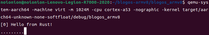
循环打点一方面是定时的功劳,另一方面是主函数中循环将系统置于低电平状态后的结果。每一次的中断处理后,系统将重新回到高电平运行状态。如果我们不采用loop轮询,将只会发生一次打点,此后及时重新到达定时器时间并发送了时钟中断,GIC也不会进行处理(因为设置的是低电平触发)。
pl011(UART)异步串行接口驱动编写
QEMU的virt机器默认没有键盘作为输入设备,但当我们执行QEMU使用-nographic参数(disable graphical output and redirect serial I/Os to console)时QEMU会将串口重定向到控制台,因此我们可以使用UART作为输入设备。
通用异步收发传输器(Universal Asynchronous Receiver/Transmitter),通常称作UART。它将要传输的资料在串行通信与并行通信之间加以转换。作为把并行输入信号转成串行输出信号的芯片,UART通常被集成于其他通讯接口的连结上。
UART作为异步串口通信协议的一种,工作原理是将传输数据的每个字符一位接一位地传输。我们在控制台中的输入,也会被它传输到qemu中。
tock-registers
在实验四中,针对GICD,GICC,TIMER等硬件我们定义了大量的常量和寄存器值,这在使用时过于繁琐也容易出错。于是我们决定使用tock-registers库。
tock-registers提供了一些接口用于更好的定义寄存器。官方说明如下:
The crate provides three types for working with memory mapped registers:
ReadWrite,ReadOnly, andWriteOnly, providing read-write, read-only, and write-only functionality, respectively. These types implement theReadable,WriteableandReadWriteabletraits.Defining the registers is done with the
register_structsmacro, which expects for each register an offset, a field name, and a type. Registers must be declared in increasing order of offsets and contiguously. Gaps when defining the registers must be explicitly annotated with an offset and gap identifier (by convention using a field named_reservedN), but without a type. The macro will then automatically take care of calculating the gap size and inserting a suitable filler struct. The end of the struct is marked with its size and the@ENDkeyword, effectively pointing to the offset immediately past the list of registers.
翻译如下:
tock-registers 提供了三种类型的内存映射寄存器:ReadWrite、ReadOnly和WriteOnly,分别提供读写、只读和只读功能。这些类型实现了可读、可写和可读写特性。
寄存器的定义是通过
register_structs宏完成的,该宏要求每个寄存器有一个偏移量、一个字段名和一个类型。寄存器必须按偏移量的递增顺序和连续顺序声明。定义寄存器时,必须使用偏移量和间隙标识符(按照惯例,使用名为_reservedN的字段)显式注释间隙,但不使用类型。然后,宏将自动计算间隙大小并插入合适的填充结构。结构的末尾用大小和@end关键字标记,有效地指向寄存器列表后面的偏移量。
根据官方的说明tock_registers作为一个示例,我们来实现pl011串口驱动。
阅读设备树关于pl011部分内容(实验二):
pl011@9000000 {
    clock-names = "uartclk\0apb_pclk";
    clocks = <0x8000 0x8000>;
    interrupts = <0x00 0x01 0x04>;
    reg = <0x00 0x9000000 0x00 0x1000>;
    compatible = "arm,pl011\0arm,primecell";
};

chosen {
    stdout-path = "/pl011@9000000";
    kaslr-seed = <0xcbd0568d 0xb463306c>;
};
由上可以看出,virt机器包含有pl011的设备,该设备的寄存器在0x9000000开始处。pl011实际上是一个UART设备,即串口。可以看到virt选择使用pl011作为标准输出,这是因为与PC不同,大部分嵌入式系统默认情况下并不包含VGA设备。
而uart寄存器表也列出了UART相关的寄存器如下图所示:
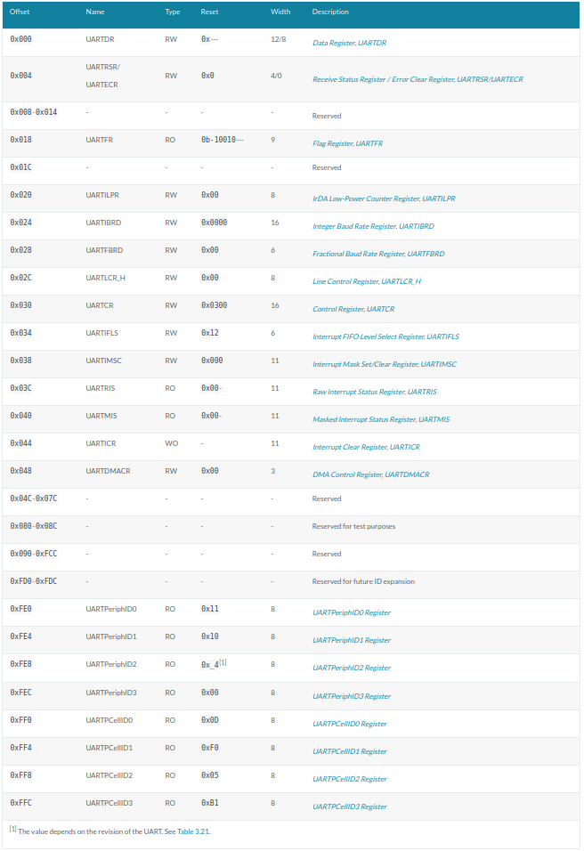
我们可以开始定义pl011驱动文件了。原则上来讲这部分内容应当定义在src/uart_console.rs中。但为了避免代码过长,我们选择重构uart_console.rs。
首先创建src/uart_console目录,并将原uart_console.rs更名为mod.rs,且置于src/uart_console目录下, 最后新建src/uart_console/pl011.rs文件。目录结构看起来像这样:
.
|____Cargo.toml
|____Cargo.lock
|____.cargo
| |____config.toml
|____aarch64-qemu.ld
|____.vscode
| |____launch.json
|____aarch64-unknown-none-softfloat.json
|____src
| |____panic.rs
| |____start.s
| |____interrupts.rs
| |____main.rs
| |____uart_console
| | |____mod.rs
| | |____pl011.rs
| |____exception.s
我们先需要在Cargo.toml中的[dependencies]节中加入依赖(这里实验指导书有误):
[dependencies]
tock-registers = "0.7.0"
根据上述tock_registers官方说明和寄存器表,我们修改src/uart_console/pl011.rs如下:
use tock_registers::{registers::{ReadOnly, ReadWrite, WriteOnly}, register_bitfields, register_structs};

pub const PL011REGS: *mut PL011Regs = (0x0900_0000) as *mut PL011Regs;

register_bitfields![
    u32,

pub UARTDR [
        DATA OFFSET(0) NUMBITS(8) []
    ],
    /// Flag Register
    pub UARTFR [
        /// Transmit FIFO full. The meaning of this bit depends on the
        /// state of the FEN bit in the UARTLCR_ LCRH Register. If the
        /// FIFO is disabled, this bit is set when the transmit
        /// holding register is full. If the FIFO is enabled, the TXFF
        /// bit is set when the transmit FIFO is full.
        TXFF OFFSET(6) NUMBITS(1) [],

/// Receive FIFO empty. The meaning of this bit depends on the
        /// state of the FEN bit in the UARTLCR_H Register. If the
        /// FIFO is disabled, this bit is set when the receive holding
        /// register is empty. If the FIFO is enabled, the RXFE bit is
        /// set when the receive FIFO is empty.
        RXFE OFFSET(4) NUMBITS(1) []
    ],

/// Integer Baud rate divisor
    pub UARTIBRD [
        /// Integer Baud rate divisor
        IBRD OFFSET(0) NUMBITS(16) []
    ],

/// Fractional Baud rate divisor
    pub UARTFBRD [
        /// Fractional Baud rate divisor
        FBRD OFFSET(0) NUMBITS(6) []
    ],

/// Line Control register
    pub UARTLCR_H [
        /// Parity enable. If this bit is set to 1, parity checking and generation
        /// is enabled, else parity is disabled and no parity bit added to the data frame.
        PEN OFFSET(1) NUMBITS(1) [
            Disabled = 0,
            Enabled = 1
        ],
        /// Two stop bits select. If this bit is set to 1, two stop bits are transmitted
        /// at the end of the frame.
        STP2 OFFSET(3) NUMBITS(1) [
            Stop1 = 0,
            Stop2 = 1
        ],
        /// Enable FIFOs.
        FEN OFFSET(4) NUMBITS(1) [
            Disabled = 0,
            Enabled = 1
        ],

/// Word length. These bits indicate the number of data bits
        /// transmitted or received in a frame.
        WLEN OFFSET(5) NUMBITS(2) [
            FiveBit = 0b00,
            SixBit = 0b01,
            SevenBit = 0b10,
            EightBit = 0b11
        ]
    ],

/// Control Register
    pub UARTCR [
        /// Receive enable. If this bit is set to 1, the receive
        /// section of the UART is enabled. Data reception occurs for
        /// UART signals. When the UART is disabled in the middle of
        /// reception, it completes the current character before
        /// stopping.
        RXE    OFFSET(9) NUMBITS(1) [
            Disabled = 0,
            Enabled = 1
        ],

/// Transmit enable. If this bit is set to 1, the transmit
        /// section of the UART is enabled. Data transmission occurs
        /// for UART signals. When the UART is disabled in the middle
        /// of transmission, it completes the current character before
        /// stopping.
        TXE    OFFSET(8) NUMBITS(1) [
            Disabled = 0,
            Enabled = 1
        ],

/// UART enable
        UARTEN OFFSET(0) NUMBITS(1) [
            /// If the UART is disabled in the middle of transmission
            /// or reception, it completes the current character
            /// before stopping.
            Disabled = 0,
            Enabled = 1
        ]
    ],

pub UARTIMSC [
        RXIM OFFSET(4) NUMBITS(1) [
            Disabled = 0,
            Enabled = 1
        ]
    ],
    /// Interupt Clear Register
    pub UARTICR [
        /// Meta field for all pending interrupts
        ALL OFFSET(0) NUMBITS(11) [
            Clear = 0x7ff
        ]
    ]
];
这里对以上读写内容也不再细讲。只需要知道的是pl011的设备基址位于0x0900_0000(第二行代码),然后根据寄存器表定义我们需要的寄存器:
register_structs! {
    pub PL011Regs {
        (0x00 => pub dr: ReadWrite<u32, UARTDR::Register>),                   // 0x00
        (0x04 => __reserved_0),               // 0x04
        (0x18 => pub fr: ReadOnly<u32, UARTFR::Register>),      // 0x18
        (0x1c => __reserved_1),               // 0x1c
        (0x24 => pub ibrd: WriteOnly<u32, UARTIBRD::Register>), // 0x24
        (0x28 => pub fbrd: WriteOnly<u32, UARTFBRD::Register>), // 0x28
        (0x2C => pub lcr_h: WriteOnly<u32, UARTLCR_H::Register>), // 0x2C
        (0x30 => pub cr: WriteOnly<u32, UARTCR::Register>),     // 0x30
        (0x34 => __reserved_2),               // 0x34
        (0x38 => pub imsc: ReadWrite<u32, UARTIMSC::Register>), // 0x38
        (0x44 => pub icr: WriteOnly<u32, UARTICR::Register>),   // 0x44
        (0x48 => @END),
    }
}
这看起来好像比实验四中对应的寄存器描述部分要复杂,但如果你熟悉了之后,基本上可以依据技术参考手册中的寄存器描述无脑写了。(很多部分可以无脑抄)
然后我们在src/uart_console/mod.rs中引入pl011.rs,并修改write_byte。
我们在前面对输出是直接定义寄存器常量的
pub fn write_byte(&mut self, byte: u8) {
        const UART0: *mut u8 = 0x0900_0000 as *mut u8;
        unsafe {
            ptr::write_volatile(UART0, byte);
        }
    }
而现在我们已经定义好了UART的寄存器表,可以选择直接调用pl011.rs中定义的寄存器:
use tock_registers::{interfaces::Writeable};

pub mod pl011;
use pl011::*;

pub fn write_byte(&mut self, byte: u8) {
    // const UART0: *mut u8 = 0x0900_0000 as *mut u8;
    unsafe {
        // pl011 device registers
        let pl011r: &PL011Regs = &*PL011REGS;
        // ptr::write_volatile(UART0, byte);
        pl011r.dr.write(UARTDR::DATA.val(byte as u32));
    }
}
由于我们较为完整的定义好了pl011寄存器组,每次调用都需要一次初始化行为。故我们还需要为Writer结构实现构造函数,并修改WRITER宏的定义:
//往串口寄存器写入字节和字符串进行输出
impl Writer {
    // ...

pub fn new() -> Writer{

unsafe {
            // pl011 device registers
            let pl011r: &PL011Regs = &*PL011REGS;

// 禁用pl011
            pl011r.cr.write(UARTCR::TXE::Disabled + UARTCR::RXE::Disabled + UARTCR::UARTEN::Disabled);
            // 清空中断状态
            pl011r.icr.write(UARTICR::ALL::Clear);
            // 设定中断mask,需要使能的中断
            pl011r.imsc.write(UARTIMSC::RXIM::Enabled);
            // IBRD = UART_CLK / (16 * BAUD_RATE)
            // FBRD = ROUND((64 * MOD(UART_CLK,(16 * BAUD_RATE))) / (16 * BAUD_RATE))
            // UART_CLK = 24M
            // BAUD_RATE = 115200
            pl011r.ibrd.write(UARTIBRD::IBRD.val(13));
            pl011r.fbrd.write(UARTFBRD::FBRD.val(1));
            // 8N1 FIFO enable
            pl011r.lcr_h.write(UARTLCR_H::WLEN::EightBit + UARTLCR_H::PEN::Disabled + UARTLCR_H::STP2::Stop1
                + UARTLCR_H::FEN::Enabled);
            // enable pl011
            pl011r.cr.write(UARTCR::UARTEN::Enabled + UARTCR::RXE::Enabled + UARTCR::TXE::Enabled);
        }

Writer
    }
}

lazy_static! {
    pub static ref WRITER: Mutex<Writer> = Mutex::new(Writer::new());
}
最后是将无用的ptr引用去除
- use core::{fmt, ptr};
+ use core::fmt;
至此,我们完成了所有关于pl011(uart)串口驱动的编写。
串口输入中断处理回调
第一节我们讲到了如何去实现timer中断的处理回调。而输入中断也是el1_irq一类的中断。回到我们修改/新增的几个函数,我们将中断实际处理部分针对输入中断做一些判断和处理即可。
输入中断初始化
同时钟中断一样,我们还是需要对输入中断进行启用和配置。修改src/interrupts.rs,新增如下内容:
// 串口输入中断号33
const UART0_IRQ: u32 = 33;

pub fn init_gicv2() {
    // ...

// 初始化UART0 中断
    // interrupts = <0x00 0x01 0x04>; SPI, 0x01, level
    set_config(UART0_IRQ, ICFGR_LEVEL); //电平触发
    set_priority(UART0_IRQ, 0); //优先级设定
    clear(UART0_IRQ); //清除中断请求
    enable(UART0_IRQ); //使能中断
}
输入中断处理回调
然后对UART的数据接收中断进行处理:修改我们的中断实际处理函数handle_irq_lines为如下,并新增输入中断处理函数handle_uart0_rx_irq:
fn handle_irq_lines(ctx: &mut ExceptionCtx, _core_num: u32, irq_num: u32) {
    if irq_num == TIMER_IRQ {
        handle_timer_irq(ctx);
    } else if irq_num == UART0_IRQ {
        handle_uart0_rx_irq(ctx);
    } else{
        catch(ctx, EL1_IRQ);
    }
}

use tock_registers::interfaces::Readable;

fn handle_uart0_rx_irq(_ctx: &mut ExceptionCtx){
    use crate::uart_console::pl011::*;
    unsafe{
        // pl011 device registers
        let pl011r: &PL011Regs = &*PL011REGS;

let mut flag = pl011r.fr.read(UARTFR::RXFE);
        while flag != 1 {
            let value = pl011r.dr.read(UARTDR::DATA);

crate::print!("{}", value as u8 as char);
            flag = pl011r.fr.read(UARTFR::RXFE);
        }
    }
}
当我们输入一个字符后,uart产生一次输入中断,而输入中断处理函数则将我们输入的字符从寄存器中取出并调用print!宏打印出来。
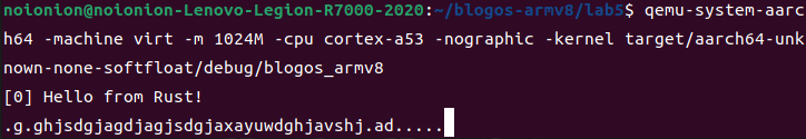
由此我们完成了输入中断的处理。我们进行代码的构建并运行:
cargo build
qemu-system-aarch64 -machine virt -m 1024M -cpu cortex-a53 -nographic -kernel target/aarch64-unknown-none-softfloat/debug/blogos_armv8
当我们随意的在控制台中敲击字符,除去时钟中断的打点输出,我们将看到我们输入的字符。此时说明我们的输入中断是成功运作的。
Recommend
About Joyk
Aggregate valuable and interesting links.
Joyk means Joy of geeK