

Applying Kappa Architecture to Make Data Available - DZone Cloud
source link: https://dzone.com/articles/applying-kappa-architecture-to-make-data-available
Go to the source link to view the article. You can view the picture content, updated content and better typesetting reading experience. If the link is broken, please click the button below to view the snapshot at that time.

Introduction
Banks are accelerating their modernization effort to rapidly develop and deliver top-notch digital experiences for their customers. To achieve the best possible customer experience, decisions need to be made at the edge where customers interact. It is critical to access associated data to make decisions. Traversing the bank’s back-end systems, such as mainframes, from the digital experience layer is not an option if the goal is to provide the customers the best digital experience. Therefore, for making decisions fast without much latency, associated data should be available closer to the customer experience layer.
Thankfully, over the last few years, the data processing architecture has evolved from ETL-centric data processing to real-time or near real-time streaming data processing architecture. Such patterns as change data capture (CDC) and command query responsibility segregation (CQRS) have evolved with architecture styles like Lambda and Kappa. While both architecture styles have been extensively used to bring data to the edge and process, over a period of time data architects and designers have adopted Kappa architecture over Lambda architecture for real-time processing of data. Combining the architecture style with advancements in event streaming, Kappa architecture is gaining traction in consumer-centric industries. This has greatly helped them to improve customer experience, and, especially for large banks, it is helping them to remain competitive with FinTech, which has already aggressively adopted event-driven data streaming architecture to drive their digital (only) experience.
In this article, we discuss the two architectural styles (Lambda and Kappa) for data processing at the edge and describe an example of real-life implementation of Kappa Architecture in a retail banking customer experience scenario.
Lambda and Kappa Architecture
Both the Lambda and Kappa architecture styles were developed to support big data analytics in processing and handling a large volume of data at a high velocity.
Lambda architecture, originally createdbyNathan Marz, addresses the challenges of the simultaneous data processing requirements in batch and real-time modesby segregating the flow of data into two distinct paths within the pattern:
- The cold path (or batch layer) performs batch processing of data in its raw form to store in batch view where latency is not a critical requirement.
- The hot path (or speed layer) performs real-time processing of the data at low latency but with lesser accuracy.
The batch layer inserts data into a serving layer which stores data in an indexed batch view for efficient querying. The speed layer updates the serving layer with the most recent data. Both of these paths converge at the analytics client applications where the client can choose to view the data either from the cold path or hot path. While there are significant advantages of Lambda architecture in terms of retaining the input data unchanged and the ability to reprocess data whenever required, it should be recognized that in Lambda architecture data processing logic, transformation logic, etc., are duplicated at two places and get implemented using two different technologies/frameworks — for example, Hadoop for batch processing and Storm for speed processing of data. This makes the implementation of this architecture become operationally complex.
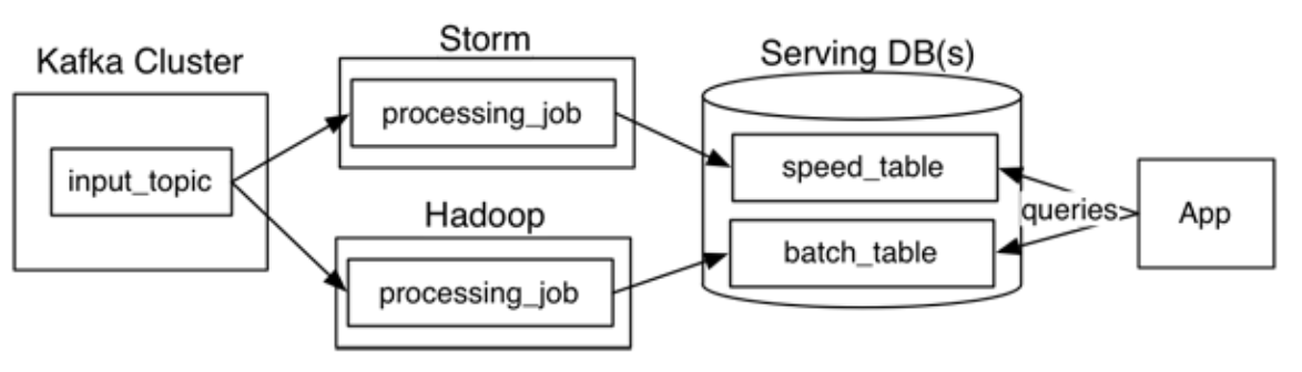
Fig 1: Lambda architecture
Kappa architecture, originally created by Jay Kreps,proposed a single data processing path using a stream processing system thatingests events of data streams from data sources into a Kafka-like distributed fault-tolerant log. An event log is immutable and ordered. Any new event is appended to change the current state of the event. As the data is persisted in the Kafka-like streaming system, reprocessing of data is possible by initiating a second instance of a data stream processing job to process the same input data and store it in a different table, if required for client application consumption.
Fig. 1: Kappa architecture
Here’s a quick side-by-side comparison of Lambda vs. Kappa architecture styles:
Architecture Style |
Pros |
Cons |
Lambda |
|
|
Kappa |
|
|
Example Implementation Scenario of Kappa Architecture
The use case is as follows: Bringing selective SoR data from the mainframe to the edge so the data can be consumed by digital channels and partner systems. In this use case, the core banking system is running on several mainframes. The idea is to apply domain-driven design principles to segment data products (along with relevant services for consuming data) and into domains like accounts, payments, agreements, and so forth. We leveraged the Kappa architecture for this use case to build a real-time data cache ahead of the system of records (SoR) to reduce “read” transaction pressure on the core banking system and ensure the customer gets consistent performance on the digital platform.
This architecture enables the agility to capture changes to the customer, account, agreements, and payment data in the core banking SoR and deliver changed data in a consistent and near real-time way, leveraging CDC (change data capture) technology to the digital access layer. This architecture is implemented in a hybrid cloud environment to meet the following requirements, where core banking SoR resides on-premises and the digital platform is hosted in a public cloud:
- Architecture should provide real-time data stream processing
- Architecture should be highly performant in terms of response times and throughput
- Data services should be highly available for business usage
- All components of the architecture must be horizontally scalable
- Expose APIs for channel applications to deliver information in real-time
The Architecture
The following diagram is an architectural overview of the solution using the Kappa pattern.
Fig 3: Kappa Architecture overview with CDC, data pipeline and event streaming elements
The following is the description of the architecture components enumerated in the above diagram:
- This layer represents multiple core banking systems and their databases containing accounts, customers, agreements, parties, deposits, etc. These data are typically updated through a message-oriented middleware (MOM), set of system APIs, or ESB. For the sake of simplicity, this layer is not elaborated in the above diagram.
- This component represents the changed data capture (CDC) layer. CDC component in this layer identifies and captures changes in the SoR database tables as and when the changes happen. It provides reliable, scalable, and low-latency replication of data between different systems hosted on-premises and on the cloud. There are several ways to track changes in the database tables due to any new business event or transactions. One of the common approaches is reading transaction log files of any database for any new database transactions of types create, delete and update. Other approaches include trigger-based CDC and comparing deltas between tables.
- This layer runs custom software routine components built with CDC libraries. This custom component reads the CDC events and translates the events to raw topics with the help of an event streaming connector (Kafka Connect). Based on the different types of core system databases there could be multiple instances of these components to get CDC data and publish it into respective topics. In this specific client scenario, components of these three layers were hosted at the on-prem data center.
- This layer hosts the entire event streaming platform which is Kafka, and it is hosted in a public cloud. There are different ways Kafka can be used in the cloud — using its managed service software from respective cloud vendors, using Confluent Kafka®, or using Apache Kafka® installed and running on a cluster of VMs in the cloud. In this client scenario, it was a custom built Apache Kafka clusters (for high performance and throughput) hosted on AWS public cloud. Based on the different types of events captured from the backend systems, this layer will process multiple “raw topics.”
- This layer runs a set of microservices termed “unpacker services” as part of a data pipeline. These microservices do the validation of the structure of the data of the raw topics against the formatted structure registered in the schema registry. In this specific implementation, this schema registry is Apache Avro®. Producers of the events also follow the same schema registry before publishing events to the topics.
- After validation and unpacking of the data, these microservices connect to different topics known as “processed topics” (shown as six in the diagram above) and publish processed data. Based on the complex data validation requirements and business rules checks, there could be one or two additional layers of topics between “raw topics” and “processed topics,” and hence there could be an additional set of microservices as part of the “data pipeline” to publish and subscribe events from those topics. There are multiple such “data pipelines” running for data events of the customer, agreement, accounts, etc., objects. For this client scenario, microservices of the data pipeline were deployed in the Red Hat OpenShift® cluster hosted in the public cloud (AWS).
- Events from the “processed topic” are read by another set of microservices termed “aggregator services” (shown as seven in the above diagram), which aggregate some of the relevant information based on data and time, agreement id, etc., and validate data against structure maintained in schema registry. These services are also deployed in Red Hat OpenShift® on the public cloud (AWS).
- Aggregator services stores data in a mesh of data cache shown as eight in the diagram. This data mesh architecture contains NoSQL schemas with domain bounded data around customer, agreement, account, and balances where respective aggregated data are stored. This data mesh can be implemented by any custom NoSQL document database or managed cache services such as Memcache, Redis, etc., by public cloud providers. For this specific client scenario, it was implemented using MongoDB.
- This layer had another set of microservices that are domain-based. These microservices help to access (read) the data from data cache and expose as APIs for consumption by external consumers such as internet banking, mobile banking, and open banking applications. These services are also deployed in Red Hat OpenShift® on the public cloud (AWS)
- APIs are exposed through an API Gateway service of the cloud provider (AWS).
Systems and components described above in four to 10 are all hosted on AWS public cloud. Several such data pipelines process business events generated from the system of records within the context of an individual domain (such as customer, account, and payment) and delivering it to the system of engagement through multiple “data ports” is essentially an approach of moving towards decentralized “data mesh” architecture from a centralized event backbone, of which Kappa architecture is the underlying foundation.
This hybrid cloud implementation of Kappa architecture significantly reduces the load on the enterprise middleware and core system database. Data events exposed as APIs also provide the capability to a bank, their partners, and other ecosystem providers in developing additional features and innovative applications.
References
Acknowledgments
The following are the architects who were involved in defining the initial architecture model that eventually evolved to this detailed implemented Kappa architecture.
- Harish Bharti, Distinguished Engineer, IBM
- Rakesh Shinde, Distinguished Engineer, IBM
Recommend
About Joyk
Aggregate valuable and interesting links.
Joyk means Joy of geeK