

Introduction to GPUs with OpenGL
source link: https://engineering.monstar-lab.com/en/post/2022/03/01/Introduction-To-GPUs-With-OpenGL/
Go to the source link to view the article. You can view the picture content, updated content and better typesetting reading experience. If the link is broken, please click the button below to view the snapshot at that time.

Introduction to GPUs with OpenGL
March 1, 2022
Nowadays, we have amazing engines like Unity and Unreal. But how does this work exactly? Learning 3D rendering or building your own engine is a daunting task.
While there are some tutorials out there, I think they are actually quite difficult if you want to fully understand the logic of it. So today, I would like to try to explain how it works at a lower level, without going too much in the details or the mathematics.
I will not show how to build a clean, production-ready app following the best practices, but rather taking a lot of shortcuts and simplifying things to make this easy to follow.
What is a GPU?
CPUs are highly specialized in computational speed and have a broad range of low-level instructions. GPUs are quite the opposite, because they are slower and simpler, but focuses on parallelization (high number of cores), and have a more limited set of instructions.
While a typical CPU today will have anywhere between 2 and 16 cores, a GPU typically have thousands of cores running operations in parallel. Both have their own independent memory and (depending on the architecture) only communicate by exchanging data via a dedicated bus.
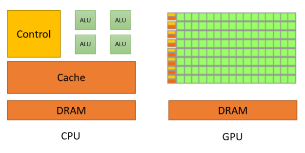 Image by
Nvidia
Image by
Nvidia
What is OpenGL?
GL stands for Graphics Library. It is a framework that makes it easier to interact with the GPU and display graphics. There are well-used alternatives like DirectX and Vulkan as well, but we'll focus on OpenGL.
OpenGL comes into two parts:
- The library itself, which you can use with pretty much any programming language. This is what runs on the CPU and sends instructions and data to the GPU.
- The shaders. Shaders are pieces of instructions (code) that are first compiled by the CPU, then sent to the GPU. This is what gets executed on the GPU side. In OpenGL, shaders are written using the GLSL language (Graphics Library Shading Language).
OpenGL also has an alternative edition called OpenGL ES (Embedded Systems). It has less features and is simplified, so that it is able to run on most mobile devices and architectures nowadays. It is also known as WebGL, and because browsers makes it easy to get started with no other setup, this is what I will use demonstrate here (with plain JavaScript). But don't worry! You can transpose the code in this article to pretty-much any programming language that you like.
Setup
I will use a very basic and single-page HTML file for all the code shown in this article. You can also find a link to the whole result at the bottom of this page.
<!DOCTYPE html>
<html>
    <body>
        <script type="text/javascript">
            const canvas = document.createElement('canvas');
            canvas.width = 640;
            canvas.height = 480;
            document.body.appendChild(canvas);

            const gl = canvas.getContext('webgl');
            if (!gl) {
                throw new Error('Unable to use WebGL. Your device may not support it.');
            }

            gl.clearColor(0, 0.5, 1, 1);
            gl.clear(gl.COLOR_BUFFER_BIT);

            // <-- Here we will add more code
        </script>
    </body>
</html>
This initializes a canvas of 640x480 pixels and a WebGL context inside of it. All the future draw operations from OpenGL will then be rendered into this canvas.
OpenGL is entirely procedural. Here we start by using clearColor which defines the color that will be used by all the future clear function calls.
Colors are defined using 4 floating-points between 0 and 1 that represents the RGBA components.
In other words, the color we are using here (0, 0.5, 1, 1) is equivalent to rgba(0, 128, 255, 1.0) (it's plain, opaque blue).
gl.clear is our first draw operation: this resets anything that might preexist in our canvas, and uniformly applies our blue color onto it.
I will not explain the meaning of the COLOR_BUFFER_BIT argument in this article because it's out of scope, but you may read the technical details here.
If you try to display this page in a browser, you will see a plain, blue canvas.
Defining a shape
We will be drawing a single rectangle covering the screen. The base element in OpenGL to draw shapes is the triangle, and every shape is made of it.
We will be using the triangle strip method to represent our rectangle. It means that we have to define our triangles with a sequence of vertices, where all triangles are connected by one vertex.
As it make things easier to understand, here is a diagram.

The rendering area (our canvas) is bound to the coordinates [-1 .. +1] on both the X and Y axes and is centered to the origin (0, 0). Shapes in OpenGL are represented using decimal numbers (floating points), not in pixels.
To draw our rectangle, we will define a first triangle (ABC), then a second one (CAD). Using a triangle strip method, we get the sequence of vertices (ABCAD).
Let's define this with a bit of code.
const positionBuffer = gl.createBuffer();
gl.bindBuffer(gl.ARRAY_BUFFER, positionBuffer);
gl.bufferData(gl.ARRAY_BUFFER, new Float32Array([
    -1, -1, // A
    +1, -1, // B
    +1, +1, // C
    -1, -1, // A
    -1, +1, // D
]), gl.STATIC_DRAW);
This creates a buffer array stored in the GPU's memory, and returns us a reference to it, as positionBuffer.
bindBuffer changes the state of OpenGL so that the following instructions (including our subsequent call to bufferData) have to use positionBuffer.
Our rectangle is then defined as a Sequence of X and Y coordinates (Xa, Ya, Xb, Yb...) as 32 bits floating-point numbers and sent to this buffer in the GPU's memory.
I will not explain what the ARRAY_BUFFER and STATIC_DRAW constants means because it is irrelevant for this article, but you may find some documentation here and here.
Now we yet have to define lots of things, but for the sake of being consistent, I will be jumping early to what will be the very last instruction of our program:
gl.drawArrays(gl.TRIANGLE_STRIP, 0, 5);
This instruction tells OpenGL to actually perform a draw call using the currently defined state and data.
The first argument is for the draw method (algorithm), and the next ones defines the range of the data to be used from our buffers. In our case, we have 5 vertices that are defined from the index 0, but this can be handy to optimize complex applications.
Types of shaders
An OpenGL program is made of two shaders:
- The vertex shader is (commonly) executed once for every vertex we want to draw. It receives some attributes as input, computes the position of this vertex in space and returns it in a variable called
gl_Position. It also defines some varyings. - The fragment shader is executed once for each pixel to be rendered. It receives some varyings as input, computes the color of this pixel and returns it in a variable called
gl_FragColor.
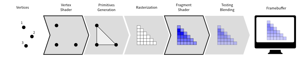
Image by Glumpy
OpenGL automatically takes care for us of everything else in the flow below!
Vertex shader
Let's start by defining a basic vertex shader.
const vertexShader = gl.createShader(gl.VERTEX_SHADER);
gl.shaderSource(vertexShader, `
    attribute vec2 position;

    void main(void) {
        gl_Position = vec4(position, 0.0, 1.0);
    }
`);
gl.compileShader(vertexShader);

// Error handling only
if (!gl.getShaderParameter(vertexShader, gl.COMPILE_STATUS)) {
    throw new Error(gl.getShaderInfoLog(vertexShader));
}
Here we are creating and compiling a vertex shader from it's source code (which is here hard-coded in a JavaScript string).
We first declare a position attribute. It is a vec2 (vector of two floating-point numbers) and will receive the (X, Y) coordinates of each vertex in our rectangle. Since we have 5 vertices in our buffer, this shader will be executed 5 times by the GPU (once per vertex)! We can also expect all 5 instances of the shader to be executed in parallel, since a GPU have so many cores.
gl_Position is always defined as a vec4 (vector of 4 floating-point numbers), but why is that? The third member is for the Z coordinate, which we set at 0 because we only have a 2D shape here.
But otherwise we could indeed define a 3D shape by having a vec3 position and adding the Z coordinate in our buffer.
The last argument is W, and this fourth dimension is used for clipping. You can read more about it here.
By default, WebGL does not output errors in the browser's console, and that's the only thing the last 3 lines are doing for us.
ℹ️ Vectors can be easily combined in GLSL. vec4(vec2(1, 2), 3, 4) being equivalent to vec4(1, 2, 3, 4) (or even vec4(vec3(1, 2, 3), 4) for 3 dimensions).
Fragment shader
Our fragment shader will be even easier.
const fragmentShader = gl.createShader(gl.FRAGMENT_SHADER);
gl.shaderSource(fragmentShader, `
    void main(void) {
        gl_FragColor = vec4(1.0, 0.0, 0.0, 1.0);
    }
`);
gl.compileShader(fragmentShader);

// Error handling only
if (!gl.getShaderParameter(fragmentShader, gl.COMPILE_STATUS)) {
    throw new Error(gl.getShaderInfoLog(fragmentShader));
}
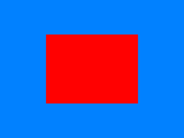
All we do here is telling OpenGL to fill every pixel in our rectangle with a red color.
The color is defined by a vec4 of 4 RGBA components in 0.0..1.0.
Creating an OpenGL program
Now that our shaders are created and compiled, we can create an OpenGL program by linking them together!
const program = gl.createProgram();
gl.attachShader(program, vertexShader);
gl.attachShader(program, fragmentShader);
gl.linkProgram(program);
gl.useProgram(program);
If it's not clear, you could compare this to building a binary executable using packages (shaders) compiled in the previous steps.
The last useProgram instruction tells OpenGL to set it's internal state so that all subsequent operations will be using this program.
ℹ️ A single application can declare and use multiple OpenGL programs. For example, it's common in a video game to have one program that renders the solid shapes, one program that renders the particles and one that renders the 2D interface (HUD/UI) on top of it.
Putting it altogether
Now that our program is created, we also need to tell it where the attribute values comes from!
const positionAttribute = gl.getAttribLocation(program, "position");
gl.enableVertexAttribArray(positionAttribute);
gl.vertexAttribPointer(positionAttribute, 2, gl.FLOAT, false, 0, 0);
The first row allows us to get a reference to the position attribute in our OpenGL program.
By then using enableVertexAttribArray, we tell OpenGL that we want this attribute to point to the value of the vertex array (which we previously bound with bindBuffer).
The last call to vertexAttribPointer allows us to tell OpenGL about the structure of our data. The parameters means that we want each instance of the vertex shader to receive 2 elements with a float type from our buffer.
In other words, one (X, Y) pair from our array will be automatically bound to the components of our vec2 (position attribute).
The last arguments (false, 0, 0) are not relevant here, but you can find more information about it here,

And we can now see a filled, red canvas. But this is boring, how are we supposed to know that we drew the rectangle properly?
We should reduce the size of the rectangle so that it does not take-up all the space. Let's see how we could do that.
Reduce the size of our rectangle?
By changing the X and Y values of each vertex to something smaller than 1, we could reduce the size of our rectangle.
That would indeed work in our case, but what if we were in a real application, and our rectangle were a 3D model with millions of vertices?
With this strategy, modifying the vertices would have to be done by the CPU (and the updated data sent again to the GPU). That would be too inefficient.
Move the rectangle away?
Let's remember what we wrote in our vertex shader.
gl_Position = vec4(position, 0.0, 1.0);
If we changed the value of Z (here 0.0) to make the rectangle far away from our viewpoint, surely it would appear smaller?
You can give it a try, and notice that Z does not actually do anything here.
For objects to appear far-away, we would need to define a perspective first.
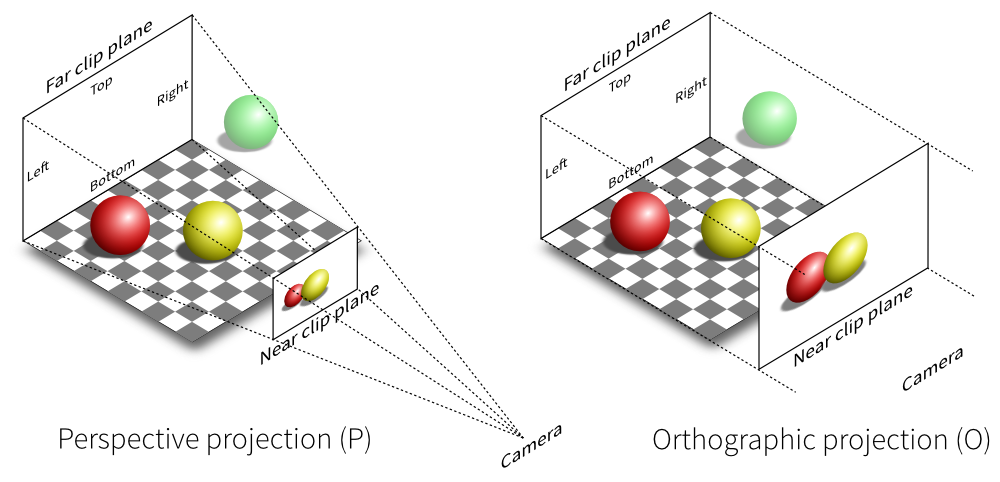 Image by
Glumpy
Image by
Glumpy
Doing that would require to set a projection matrix, which I will keep out of the scope of this article. You may however follow the tutorial on MDN to learn more about it.
Scale down the rectangle?
There is a last option in our case: make the shader scale down the vertices of our rectangle.
While this may sound similar to the first option, it's a trivial operation for a GPU, and can be done very easily without any performance issue.
I also want to take this as an opportunity to introduce uniforms.
Uniforms
We said earlier that the vertex shader receives attributes while the fragment shader receives varyings. But there is a third category of inputs in OpenGL, called uniforms. Uniforms are very much like constants, except that the values are not hard-coded, but programmatically defined before the execution of the OpenGL program.
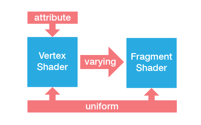 Image by
Subterranean Flower
(in Japanese)
Image by
Subterranean Flower
(in Japanese)
The value of uniforms are always ... uniform among all instance of the vertex or fragment shaders (but can still be different for each instance of the OpenGL program itself.
Let's now modify our vertex shader:
attribute vec2 position;

uniform float scale;

void main(void) {
    gl_Position = vec4(position * scale, 0.0, 1.0);
}
Our scale uniform will receive a scaling factor (for example 0.5), which is then multiplied to the X and Y coordinates of each vertex.
Note: In GLSL, (vec2(x, y) * a) is equivalent to vec2(x * a, y * a).
All remains to do is assign a single floating-point (1f: '1 float') value to this uniform:
const scaleUniform = gl.getUniformLocation(program, "scale");
gl.uniform1f(scaleUniform, 0.5);
And voilà! You should now be able to see a red rectangle in the middle of the blue canvas!
Gradient colors
We are going to replace the red color with a gradient of different colors by using varyings.
Varyings are values passed from the vertex shader to the fragment shader. While there is no direct mapping between a vertex and a pixel, OpenGL can automatically interpolate the values for us!

This property of varyings is very useful, and applies to each member of a vector. In other words, if we assign a color to each vertex, the components will be interpolated for each pixel, thus creating a gradient.
This technique is commonly used to get and display a specific pixel from a texture, or to apply per-vertex shading.
Let's have a look at our rectangle again.
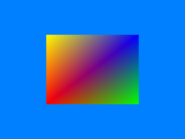
We are going to set A to red, B to green, C to blue and D to yellow. The data structure is almost identical to our vertices, but we now have vectors of 3 values (R, G and B components between 0 and 1) for each vertex instead of two X and Y values.
const colorBuffer = gl.createBuffer();
gl.bindBuffer(gl.ARRAY_BUFFER, colorBuffer);
gl.bufferData(gl.ARRAY_BUFFER, new Float32Array([
    1, 0, 0, // A = red
    0, 1, 0, // B = green
    0, 0, 1, // C = blue
    1, 0, 0, // A = red
    1, 1, 0, // D = yellow
]), gl.STATIC_DRAW);
const colorAttribute = gl.getAttribLocation(program, "color");
gl.enableVertexAttribArray(colorAttribute);
gl.vertexAttribPointer(colorAttribute, 3, gl.FLOAT, false, 0, 0);
In our vertex shader, we receive the color as a vec3 attribute, and assign it's value to a varying.
attribute vec2 position;
attribute vec3 color;

varying mediump vec3 vColor;

uniform float scale;

void main(void) {
    gl_Position = vec4(position * scale, 0.0, 1.0);
    vColor = color;
}
Varyings must always specify a precision (lowp, mediump, highp). This controls the number of bits that will be used internally for each value. It can greatly impact the performance (depending on the complexity of the program and the hardware). But in our example, it does not matter, so I'm using a medium precision.
Since OpenGL does all the work for us, the fragment shader only adds an alpha channel (1 = opaque) and returns the color.
varying mediump vec3 vColor;

void main(void) {
    gl_FragColor = vec4(vColor, 1.0);
}
You should now see our rectangle with smooth gradient colors like this:
Conclusion
I tried to focus on what I consider to be the fundamentals to understand how all of this works. There are many things I wish I could explain further, like animations, shading (light effects), particles, camera (viewpoint and projection matrices...), and more broadly the architecture necessary to handle this at large scale (like a video game or 3D engine) But this could not possibly fit in the format of a blog article.
You can see the complete result of this article here and debug or experiment by yourself.
Also, you can have a look at the resources linked below if you want to explore further.
Links and credits
- An article from Nvidia about the history of GPUs.
- Another great article from which I took the OpenGL pipeline and projections images.
- You can find a more advanced WebGL tutorial on MDN.
- webglreport.com gives you some insights on what is supported by your device.
Recommend
About Joyk
Aggregate valuable and interesting links.
Joyk means Joy of geeK