

Using Compute Module 4 IO Board pins as an ATX case front panel header
source link: https://www.jeffgeerling.com/blog/2021/using-compute-module-4-io-board-pins-atx-case-front-panel-header
Go to the source link to view the article. You can view the picture content, updated content and better typesetting reading experience. If the link is broken, please click the button below to view the snapshot at that time.
Recently I built the Seaberry, a Raspberry Pi Compute Module 4 mini ITX motherboard into a PC case (video coming soon...), and got the case power button, power LED, and activity LED all wired up to the Pi:
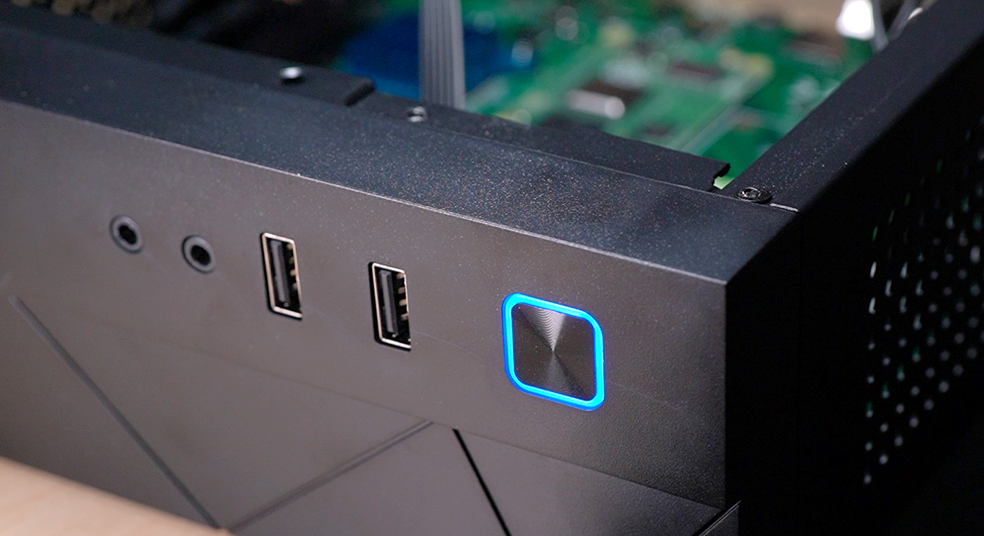
I used the GPIO and 14-pin header present on the Seaberry (which conveniently are identical to the headers on the official CM4 IO Board), and wound up with a fully functionality power button, power LED, and activity LED!
Here's how I did it:
Power button
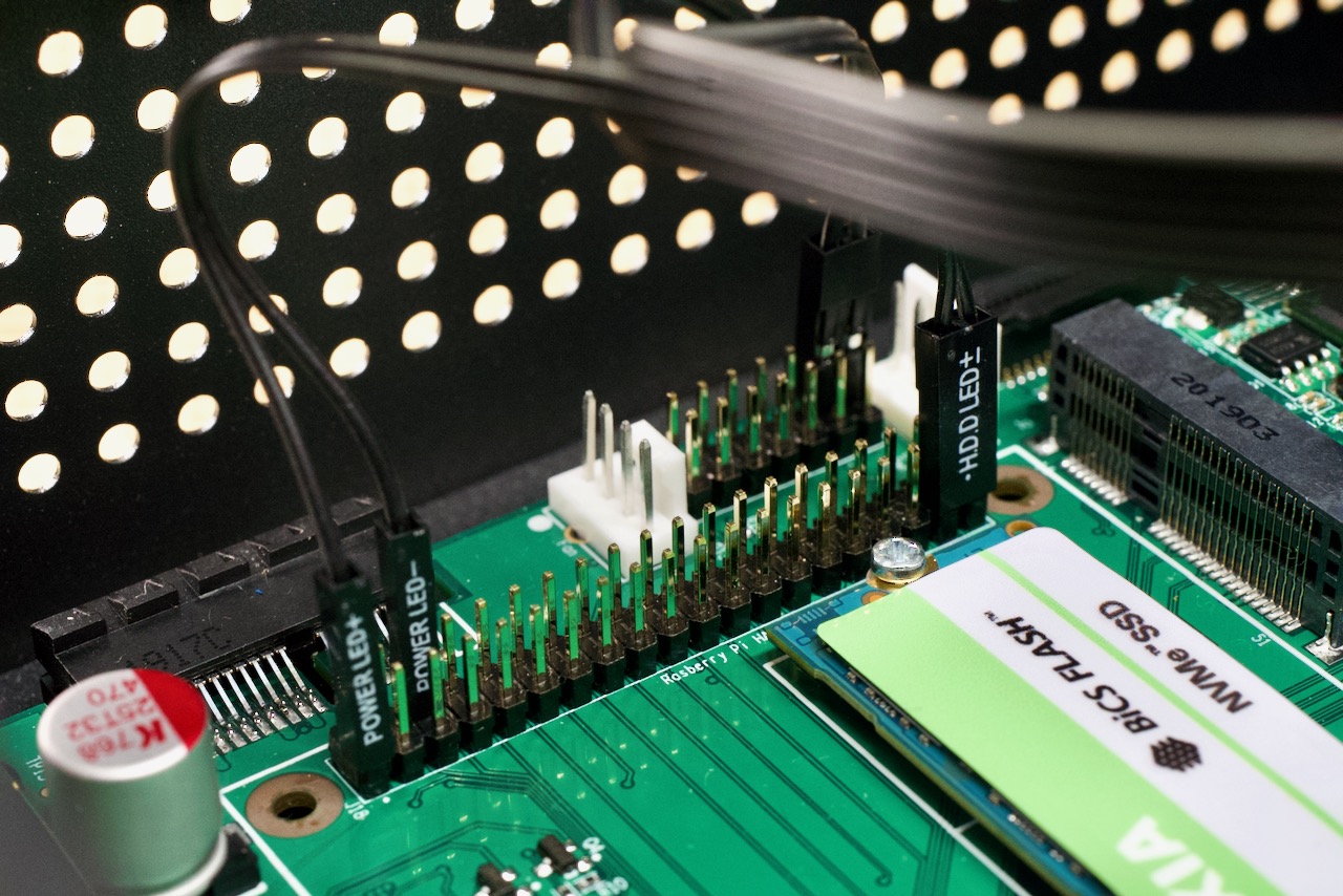
To get the power button working, you need to connect the case's front panel 'power switch' connector to pins 12 and 14 (GLOBAL_EN and GND), as seen in the top middle of the above picture.
This requires the 14-pin header be exposed on your Compute Module 4 board—some boards don't expose it, so you'd have to do some digging to find where GLOBAL_EN is exposed (if at all!).
Note: If you wire up the power button this way, it's actually more of a 'reset/power' button. Basically, the way GLOBAL_EN works, if you short it to ground, it will hard-reboot the Pi. For a safer power button that doesn't also reset the Pi, connect it to pins 13-14 instead. This way the power button will only boot the Pi when it's been shut down normally.
Power LED
For the rest of the connections, I will be referring to pins on the Raspberry Pi GPIO header.
This is a little bit of a hack... basically I'm jumping pin 1 (3.3V +) and pin 6 (GND -) directly to the front cover power LED. Technically you might consider a resistor in series to protect the LED further, but it seems many ATX/ITX case LEDs already have a resistor on their little breakout board.
The downside to this approach is that at least with the Seaberry board, the 3.3V rail on the IO board's GPIO is always powered if there is power plugged in at all. So this LED doesn't truly show the Pi's 'powered on' state. To do that, I'd consider wiring up a GPIO pin and having software turn it on at boot (though it still wouldn't perfectly reflect when the Pi's powered on, because there would be a delay between power on and when the LED comes on).
Activity LED (or 'HDD' lol)
This one isn't too hard either, since you can add an overlay in the Pi's configuration to direct the activity LED to any GPIO pin.
To make things easy, since my case's 'HDD LED' plug is bundled together (+/- in a 2-pin connector), I added the following to my /boot/config.txt:
dtparam=act_led_gpio=26
Then I plugged in the HDD ACT + to pin 37 (GPIO 26), and HDD ACT - to pin 39 (GND).
Recommend
About Joyk
Aggregate valuable and interesting links.
Joyk means Joy of geeK