

Inside a 20-Watt Traveling Wave Tube Amplifier from Apollo
source link: http://www.righto.com/2021/07/inside-20-watt-traveling-wave-tube.html
Go to the source link to view the article. You can view the picture content, updated content and better typesetting reading experience. If the link is broken, please click the button below to view the snapshot at that time.

Inside a 20-Watt Traveling Wave Tube Amplifier from Apollo
How did the Apollo astronauts communicate on their trip to the Moon, 240,000 miles back to Earth? They used a 32-pound amplifier, built around a special kind of vacuum tube called a traveling-wave tube. In this blog post, I look inside this amplifier and explain how the traveling-wave tube works.

Surprisingly, this amplifier only produced 20 watts of power, not much more than a handheld walkie-talkie.1 You might wonder how a 20-watt signal could be received all the way from the Moon. To pick up the weak signal, NASA built a network of 26-meter (85-foot) dish antennas that spanned the globe, with ground stations in Spain, Australia, and California. For the signal to the spacecraft, the ground stations broadcast a strong, focused 10,000-watt signal that could be picked up by the spacecraft's small antennas. Additional ground stations with smaller 9-meter (30 foot) antennas filled in coverage gaps, along with tracking ships and airplanes.2
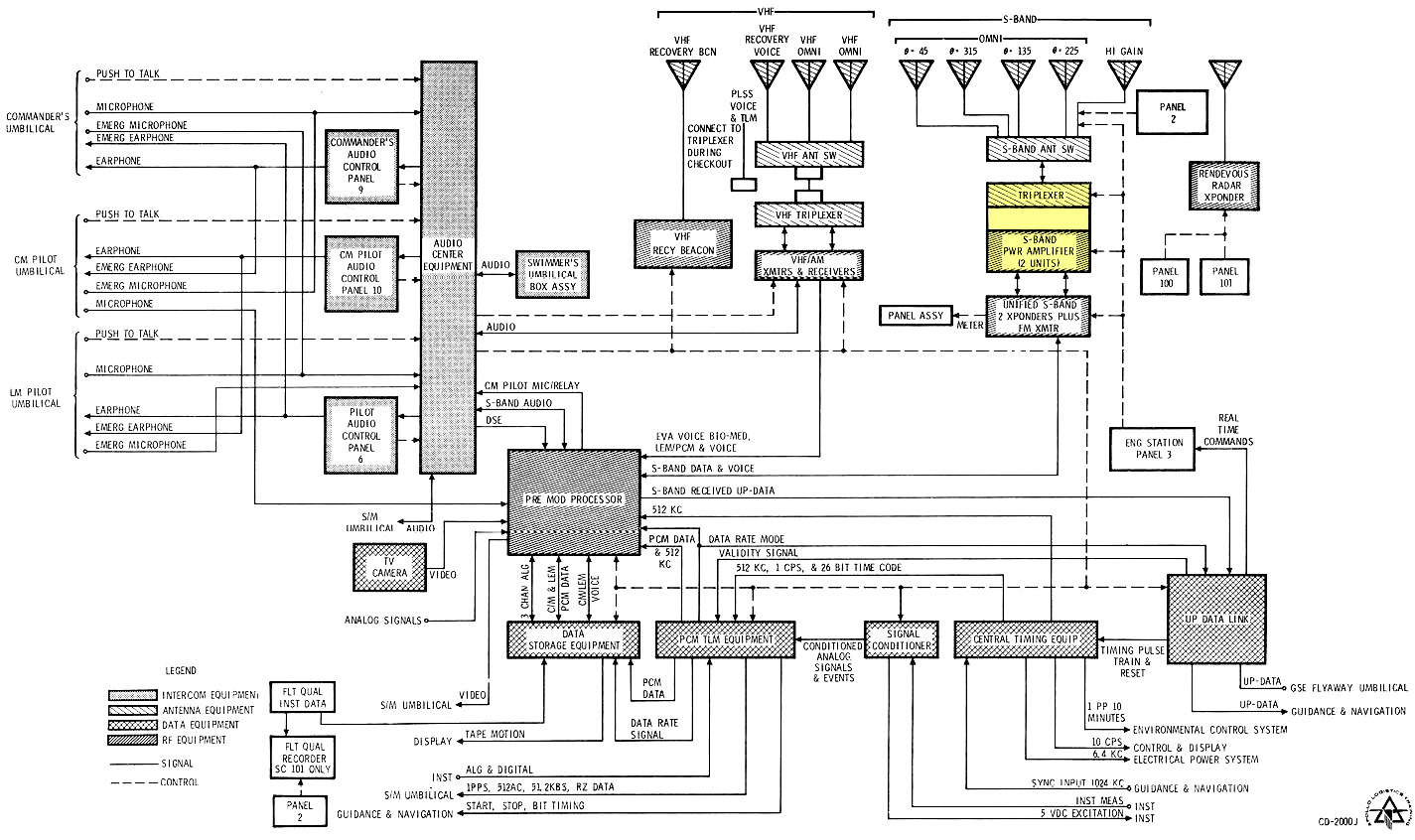
The communication system on Apollo was very complex, as shown in the diagram below. The amplifier, highlighted in yellow, was just one component of this system (which I'm not going to try to explain here). Most communication went over the "Unified S-Band", which sent voice, data, telemetry, TV, control, and ranging through one unified system. In comparison, the Gemini missions used separate systems for different purposes. (S-band refers to the microwave frequency band used by this system.)
Inside the amplifier
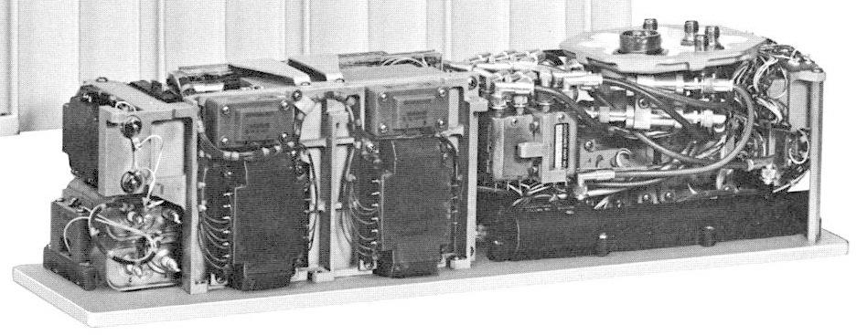
The amplifier was built by Collins Radio, a company that had a large role in the space program.3 (Collins claims that from Mercury and Gemini to Apollo, every American voice transmitted from space was via Collins Radio equipment.) The photo below shows the amplifier with the cover removed, showing the circuitry inside. Note the tangles of coaxial cables for the high-frequency RF signals. The "Danger High Voltage" warning is due to the thousands of volts required by the traveling-wave tubes.
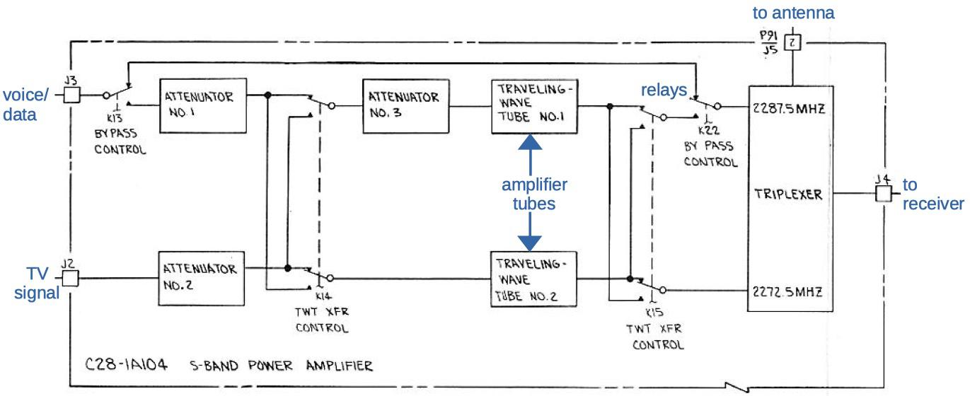
The block diagram below shows the structure of the amplifier,4 centered on the two traveling-wave tubes that perform the amplification. The amplifier takes two inputs: voice/data and the TV signal. In normal use, one tube amplifies the voice/data signal and the other amplifies the TV signal. An important feature is that either signal can be sent to either tube, or the amplifier can be bypassed entirely. This allows communication if a tube fails, or even if the amplifier entirely fails. The signals are directed by RF relays, electrically-controlled switches. The triplexer sends the two amplified signals to the antenna, and directs the signal from the antenna to the receiver.)
The photo below shows the amplifier with the case removed. (We were unable to disassemble the amplifier completely so this photo is from the documentation.5) The traveling-wave tube is the black cylinder at bottom right, about 10 inches long. The second tube is in the same position on the back of the amplifier.
How a traveling-wave tube works
The traveling-wave tube (TWT) is the heart of the amplifier. TWT systems have been popular for satellites because they are compact and provide high amplification with very wide bandwidth.7 They are still widely used in satellites, radar, and other systems.
A traveling-wave tube uses an interesting technique to amplify the input RF signal, different from typical vacuum tubes. It creates a beam of electrons and transfers energy from this beam to the RF signal. In more detail, an electron gun shoots electrons down the tube, (a bit like a CRT). As these electrons travel through the tube, they interact with the RF signal and bunch together, transferring energy to the RF signal.6
The problem is that the electron beam and the RF signal need to travel at approximately the same speed in order to interact, but the electron beam travels at about 10% the speed of light,8 while the RF signal travels at the speed of light. The trick is to put the RF signal through a helix, wrapped around the beam. Because the RF signal travels through the long helix rather than in a straight line, its path through the tube is slowed. With the proper helix design, the RF signal and the electron beam travel at approximately the same net speed down the tube, allowing them to interact.
The diagram above shows the components of the traveling wave tube in detail. The heart of the TWT is the drift tube that holds the electron beam, wrapped in the helix for the RF signal. At the left, the electron beam is created by the components of the electron gun (heater, cathode, and electrodes). The RF input and output provide the connections to the helix for the signal that is being amplified. The collector absorbs the weakened electron beam after it has passed through the tube. Finally, the permanent magnets keep the electron beam focused through the tube.
It's hard to see the traveling-wave tube inside the amplifier, since it is mounted at the bottom under a bunch of coaxial cables; the photo below is the best I could do. The tube looks like a black cylinder, but you can see the coaxial cables attached at the left and right.
Other parts of the amplifier
Next, I'll briefly describe the other circuitry inside the amplifier. A traveling wave tube requires high voltage to accelerate the electron beam. The photo below shows two of the power supply transformers. The amplifier was powered with 115 volts AC, 3-phase at 400 cycles per second. It also used 28 volts DC for the control circuitry. Note the circuitry encased in plastic at the bottom of the photo.
As described earlier, the RF relays switch signals between the two tubes to provide redundancy. The relays (below) are the fairly large square units with coaxial cables attached. These relays are more complex than typical relays because they must transfer gigahertz RF signals. The internal wiring is constructed from metal strips between double ground planes along with waveguides.
Another interesting component of the amplifier is the triplexer, a special RF component that connects the antenna to the amplifier. The idea of the triplexer is that it has three ports, each for a different frequency, and keeps the signals on each port separate from each other. Specifically, it combines the main 2287.5 megahertz signal with the TV's 2272.5 megahertz signal and sends these to the antenna. The signal from the ground is at 2106.4 megahertz; the triplexer directs this signal from the antenna to the receiver. Internally, the triplexer has band-pass filters for each frequency, providing a large amount of isolation (60 dB) between its three ports.
The triplexer is the metal box in the photo above. Note the coax connections with the antenna connection labeled. Although the triplexer says "Danger High Voltage" on top, this refers to the surrounding power supply circuitry, not the triplexer itself.
Controlling the amplifier
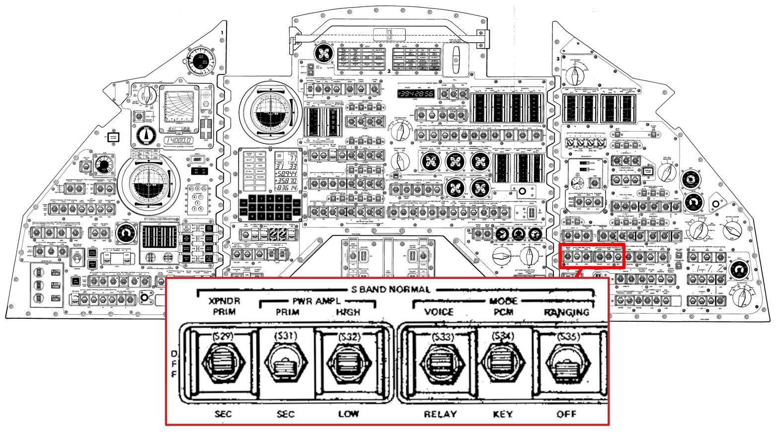
The astronauts had control switches in the Command Module to turn the power amplifier on and off, and switch between the primary and secondary tubes. The diagram below shows the location of these switches, marked PWR AMPL. The PRIM/SEC selects which tube was used for the main signal and which was used for the TV signal. The HIGH/OFF/LOW switch selected the power output level for the amplifier. When the amplifier was off, the input signal was connected directly to the antenna, bypassing the amplifier.
Conclusion
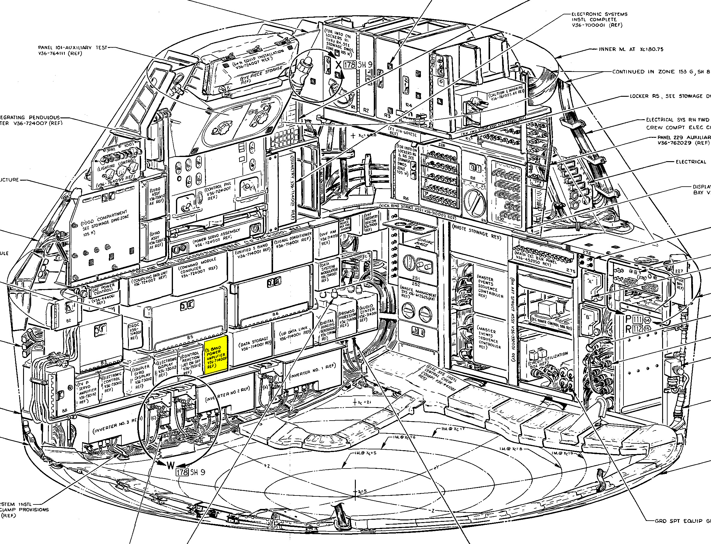
This power amplifier illustrates the complexity of the communication systems for Apollo.9 Even though the amplifier is complex internally with redundant traveling-wave tubes, it is just one of many pieces of hardware. The diagram below shows the Command Module's equipment bay, with the amplifier highlighted in yellow. (The Apollo Guidance Computer was directly above the amplifier, two rows up.)
We are currently investigating the possibility of powering up this amplifier to see if it still operates. I announce my latest blog posts on Twitter, so follow me @kenshirriff for updates. I also have an RSS feed. Thanks to Steve Jurvetson for loaning me this amplifier. Thanks to Spaceaholic and Mike Stewart for providing diagrams and the Collins Aerospace Museum for additional information.
Notes and references
-
Walkie-talkies typically use 0.5 to 5 watts of power, with some models providing 8 watts, mostly limited by FCC regulations. There are a few 20-watt or even 25-watt handheld radios. ↩
-
This photo shows the Vanguard tracking ship. This ship was a surplus tanker from World War II that was repurposed as a missile tracking ship by covering it with antennas. NASA used the ship for communication with Apollo, and the ship was scrapped in 2013.
The Vanguard ship, from Wikimedia. -
The document Collins S-Band Power Amplifier has technical specifications for the amplifier. The presentation Collins Role in Space Communications describes the Collins equipment used in Mercury, Gemini, and Apollo. Collins built equipment for the spacecraft and transmitting and receiving equipment on the ground. ↩
-
Here's a more detailed diagram of the power amplifier circuitry. This diagram shows the power supply and control circuitry in more detail. In particular, the circuitry lets the tubes heat up for 90 seconds before use. Circuitry also shuts down the power if there is a fault or loss of a power phase.
The power amplifier diagram. From "Apollo Logistics Training", courtesy of Spaceaholic. -
The Collins photo makes it look like you can simply remove the case from the amplifier. However, the photo is misleading since the amplifier doesn't come apart like that. We attempted to remove the amplifier from the case, but it is fastened with many inaccessible screws and some components are glued down. We suspect that the amplifier was assembled inside the case, making it very difficult to perform any pre-launch maintenance. We gave up on disassembling the amplifier completely, which is why all our photos show the view from the top. ↩
-
The interaction between the electron beam and the RF signal in the helix is complex, but the net result is that energy is transferred from the beam to the signal. Specifically, the electric field from the RF signal produces positive and negative waves. These accelerate and decelerate the electrons, causing them to bunch together. (On the whole, the electron beam decelerates more than it accelerates, so it loses energy.) The moving bunches of electrons induce more current in the helix, strengthening the RF signal. The result is a feedback loop, causing the RF signal to grow exponentially as it travels through the tube.
For more information on how traveling-wave tubes work, see Traveling Wave Tube, Recent theory of traveling-wave tubes, or this long presentation. ↩
-
A traveling-wave tube can amplify a large range of frequencies (i.e. it has a high bandwidth) because it doesn't have any resonant elements (unlike a klystron, for instance). Thus, it doesn't need to be tuned to a particular frequency. ↩
-
Ignoring relativistic effects, the speed of an electron beam accelerated by a voltage is given by
Equation for electron beam speed.where v0 is the velocity, Vb is the voltage, e is the charge of an electron, and me is the mass of an electron. For example, applying 6000 volts yields an electron speed of 46,000 km/second, about 15% the speed of light.
This equation is a rearrangement of the kinetic energy from the velocity and the energy from the voltage potential difference.
Kinetic energy equation.In the traveling-wave tube, the electron beam must be slightly faster than the (net) RF signal speed so the beam will transfer energy to the RF signal as the beam is slowed.
-
For more information on Apollo communication, see Apollo Experience Report - S-Band System Signal Design and Analysis. See also CSM Functional Integrated System Schematics and Command/Service Module Systems Handbook. ↩
Recommend
About Joyk
Aggregate valuable and interesting links.
Joyk means Joy of geeK