

Network and Security Virtualization
source link: https://blogs.vmware.com/networkvirtualization/2021/06/introducing-ospf-support-in-nsx-t-3-1-1.html/
Go to the source link to view the article. You can view the picture content, updated content and better typesetting reading experience. If the link is broken, please click the button below to view the snapshot at that time.

Introducing OSPF Support in NSX-T 3.1.1
NSX-T has revolutionized the data center and plays a key role in modern data center fabrics. Its unmatched capabilities are key elements in any effort to modernize networking in the data center.
NSX-T version 3.1.1 will go down as a critical milestone in this journey, as it supports OSPF version 2.
Based on RFC 2328, Open Shortest Path First Version 2 (OSPF v2) provides fast convergence, scalability, and is widely known among network architects and their operations teams. As a result, it is one of the most popular link state routing protocols in enterprise networks and data centers.
Interconnecting your physical networking fabric with NSX-T was possible using static routes and BGP. OSPF is now an option to consider leveraging dynamic routing protocols in the data center. By supporting OSPF as a dynamic routing protocol, existing NSX for vSphere customers can migrate seamlessly to NSX-T.
In this blogpost, we will demonstrate how to implement OSPFv2 within NSX-T in your data center.
OSPF Support in NSX-T
Providing connectivity between users and applications in a data center is crucial. The main purpose of any routing protocol is to dynamically exchange or share information regarding the reachability of a network.
Routers using a link state dynamic routing protocol like OSPF exchange a complete topology of the network (state of each link) with their direct neighbors. This information is then shared among all the routers in the area and stored in a link state database (LSDb).
With the topology mapped, each OSPF routers compute the shortest path to each destination using the Dijkstra algorithm.
OSPF v2 is supported on NSX-T starting with NSX-T 3.1.1. Figure 1 demonstrates that the protocol can be enabled on external interfaces hosted on Tier-0 gateways.
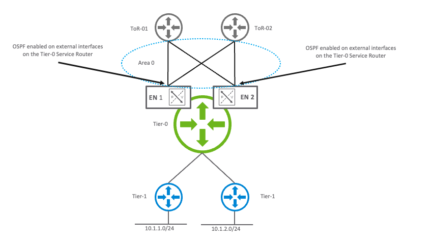
Figure 1 – OSPF enabled on external interfaces on a Tier-0 logical router
OSPF Areas
A Tier-0 gateway, can belong to one single OSPF area. Figure 2 shows the different OSPF areas supported by the Tier-0 gateway:
- Standard Area:
- Non-Backbone area that needs to be connected to a backbone area (0 or 0.0.0.0) using an Area Border Router (ABR).
- Backbone Area:
- This area contains a detailed knowledge of the entire topology (multiple areas).
- Not So Stubby Area (NSSA):
- This area does not allow the Type 5 LSA. It is replaced by a Type 7 LSA (NSSA LSA) when LSAs for external prefixes need to be injected in the OSPF network.

Figure 2 – OSPF areas supported in NSX-T – standard – backbone – NSSA
OSPF Route Types
In a standard or backbone area, the Tier-0 service router is an autonomous system boundary router (ASBR) that redistributes its routes into the area it is connected to. Therefore, it injects LSAs type 5 with an external type of 2 and a cost of 20.
On the other side, if the Tier-0 service router is connected to an NSSA, the routes will be redistributed as N2 (LSA type 7).
Figure 3 shows the different types of LSAs that can be redistributed within a standard area or within a “Not So Stubby Area”.
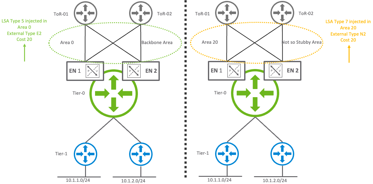
Figure 3 – Redistribution of routes within a standard area and within an “Not So Stubby Area”
OSPF Network Types
In the data center, OSPF network types can be categorized into two distinct classes:
- Point-to-Point
- Broadcast
Figure 4 demonstrates an example of a supported OSPF network type in an NSX-T topology.
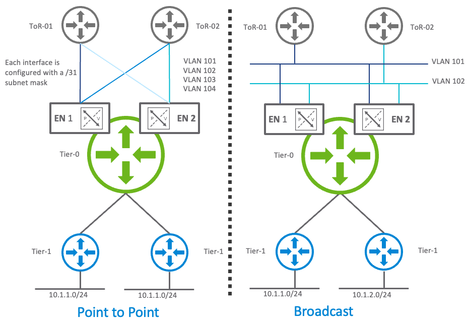
Figure 4 – OSPF network types supported
OSPF Point-to-Point Network Type
On a point-to-point segment, there is no DR or BDR election and only two OSPF routers can be present. These two OSPF routers establish an adjacency between themselves. This OSPF point-to-point network mode greatly simplifies troubleshooting and the overall OSPF topology. In this topology there is no “2 way” adjacency between the Tier-0 service routers.
Figure 5 shows the OSPF adjacency formed between a Tier-0 gateway hosted on two edge nodes and two top of rack switches.
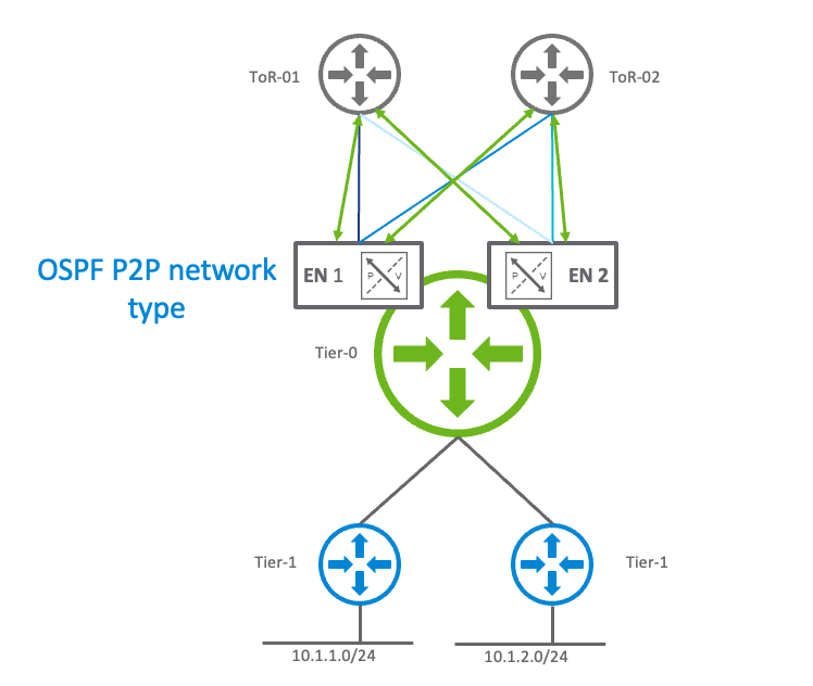
Figure 5 – OSPF adjacencies – P2P network type
Figure 6 shows the OSPF adjacencies visualization between the top of rack switches and the Tier-0 gateways.
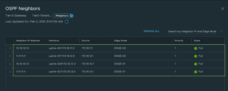
Figure 6 – OSPF Adjacencies in “Full” state in OSPF P2P network type
OSPF Broadcast Network Type
On a multi-access segment (Broadcast OSPF network type), OSPF elects a designated router (DR) and a backup designated router (BDR) to reduce the number of adjacencies. OSPF routers on the segment will fully establish an adjacency with the DR and BDR only.
As demonstrated in Figure 7, the Tier-0 service routers hosted on both Edge Node 01 and Edge Node 02 will fully establish an adjacency with both ToR-01 (DR) and ToR-02 (BDR) (represented as the green adjacencies in Figures 7 and 8).
The Tier-0 service router hosted on Edge Node 01 will be able to see the OSPF Hello packets sent on vlan 101 and vlan 102 by the Tier-0 service router hosted on the Edge Node 02, but their adjacency state will stay in the “2 way” state and they will not exchange their LSDatabase. From an OSPF perspective, the Tier-0 service router’s type is considered “DROther”.
The “2 way” adjacencies on Tier-0 are represented in red on Figures 7 and 8.

Figure 7 – OSPF adjacencies between the Tier-0 gateway and the physical fabric – broadcast network type
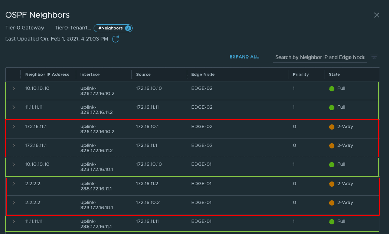
Figure 8 – OSPF adjacencies in “Full” and “2-Way” state in the OSPF broadcast network type
OSPF Supported Topologies
OSPF Adjacencies
Table 1 represents the default timers used in OSPF for both the point-to-point and broadcast OSPF interface type. According to these OSPF timers, it will take up to 40 seconds to detect the failure of a neighbor.
Table 1 – OSPF default timers OSPF Timers Default Timer in seconds OSPF Hello interval 10 OSPF Dead interval 40To provide a faster detection time, NSX-T supports BFD which will trigger OSPF, bringing down the adjacency in case of a top of rack switch failure. Since NSX-T 3.0, the BFD timers have been improved to provide best-in-class neighbor failure detection time. Table 2 states the different values supported by the edge node on both bare metal and virtual machine form factors.
Table 2 – BFD Timers support within NSX-T Edge Node Form Factor BFD Hello Timer Multiplier Failure detection Bare Metal 50ms 3 150 ms Virtual Machine 500ms 3 1500 msOSPF is supported on both active/standby and active/active topologies. Stateful services can be used on a Tier-0 service router when high availability status is running in active/standby mode.
Both the OSPF point to point and broadcast network types are available in either active/standby or active/active high availability Tier-0 topologies.
Active/Standby Topologies
In the active/standby topology represented in Figure 9, the Tier-0 gateway running in standby mode is running the OSPF process and establishes an adjacency with the top of rack switches
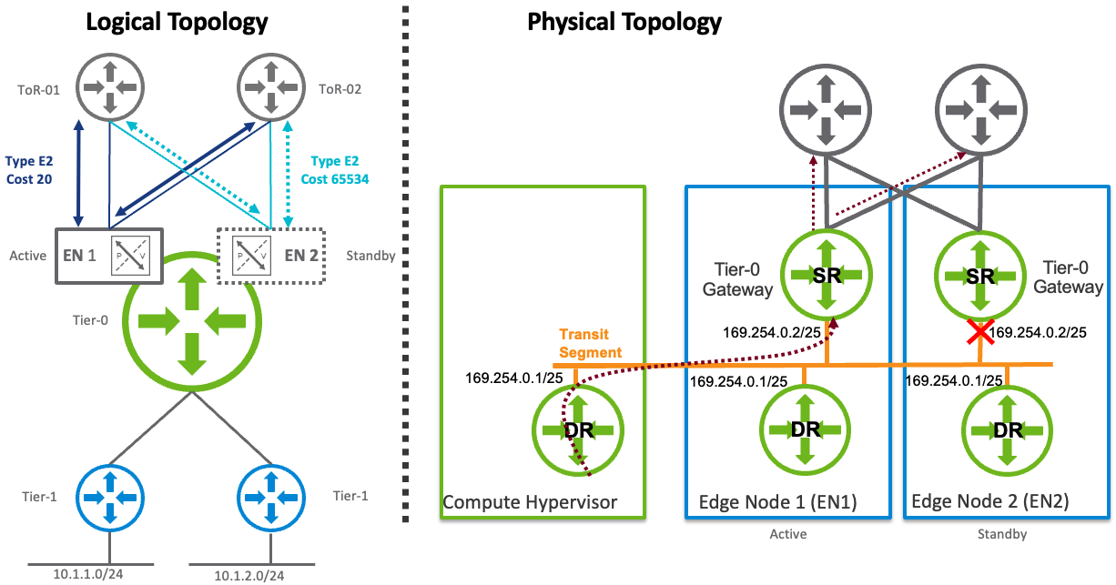
Figure 9 – active/standby OSPF topology
As mentioned previously, the routes redistributed into the OSPF process are advertised as E2 (or N2). The traffic destined for the Tier-0 DR must be sent from the top of rack switch to the active Tier-0 gateway. The active Tier-0 SR advertises its prefixes with a cost of 20 and a type of “E2” while the standby Tier-0 service router advertises the same prefixes with a cost of 65534. As a result, both top of rack switches prefer the path through the active Tier-0 service router.
For outbound traffic, the active Tier-0 service router can leverage ECMP to multiple top of rack switches. Identical routes must be advertised by the top of rack switches using the same metric.
Active/Active Topologies
In an active/active topology, ECMP can be leveraged between the top of rack switches and the Tier-0 gateways as well as between the Tier-0 DR and the Tier-0 SR in a single tier routing topology. The topology demonstrated on Figure 10 allows the networking traffic to be optimized and load-balanced throughout the entire NSX-T domain. Applications and users will get the best of the network using this topology.
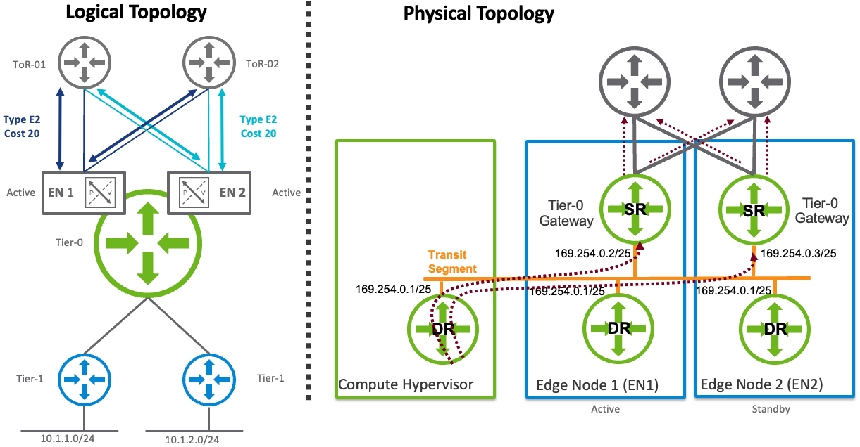
Figure 10 – active/active OSPF topology
Traffic sent by the distributed router towards the physical networking fabric (south to north) will leverage ECMP in this case and will be load-balanced across all physical paths towards the service routers. The Tier-0 SR supports up to eight ECMP paths in either active/active or active/standby topology.
Since the LSDatabase (LSDB) is identical across all the OSPF routers in an area, it is not necessary to establish an OSPF adjacency between the different Tier-0 service routers. Inter-SR routing is only useful and available in BGP architectures.
OSPF Graceful Restart
OSPF graceful restart (GR) helper mode is supported in NSX-T 3.1.1. During a graceful restart, the Tier-0 gateway running in helper mode does not stop sending networking traffic to the top of rack switch that is experiencing a control plane failover.
OSPF Redistribution
Since OSPF is another dynamic routing protocol supported on the NSX-T Tier-0 gateway, redistribution into a specific protocol is now possible. NSX-T provides more flexibility, as administrators have the choice to either redistribute their routes into BGP or into OSPF. Redistributing routes using route maps is supported. In the case of an eBGP multi-hop architecture, it is possible to use OSPF to learn the BGP peer IP addresses.
Figure 11 shows all the route types that can be redistributed in either OSPF or BGP on a Tier-0 service router.

Figure 11 – Redistribution route types
Figure 12 demonstrates that a single, simple step is needed to enable prefix redistribution into OSPF or BGP. Route maps can be selected in this particular networking construct to provide more granularity on redistributed routes.

Figure 12 – Routes redistributed in BGP/OSPF
OSPF Summarization
By default, an OSPF router advertises all its LSAs in the area it is connected to.
Since the NSX-T Tier-0 gateway is an ASBR, it can perform route summarization and advertise a summary route using a single LSA. Summarization is recommended in large scale environments to reduce LSA flooding and preserve CPU and memory resources on the networking appliances.
Figure 13 represents an active-active topology with 256 contiguous subnets (10.0.0.0/24 to 10.0.255.0/24). Each subnet is known as “T1c” (Tier-1 connected route) from a Tier-0 SR standpoint. When the Tier-0 SR redistributes these routes into OSPF, it can summarize the 256 “Type 5 LSAs” into a single Type 5 LSA with the following parameters:
- LSA type: AS-external-LSA
- Network mask: /16
- Metric type: E2
- Cost: 20
- Forward address: 0.0.0.0
- External route tag: 0
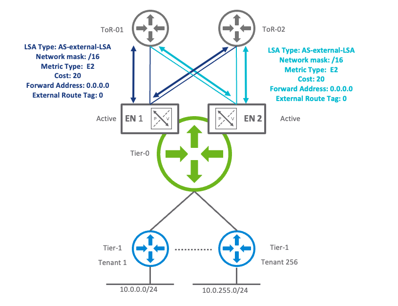
Figure 13 – OSPF Summarization
Next Steps
If you are interested in learning more or in trying out NSX-T, here are some useful links:
NSX-T Data Center Product Page
NSX-T Data Center Design Guide
NSX-T Data Center Documentation
What’s new in NSX-T 3.1.1 (Slides)
Recommend
-
7
AWS, Ansible and Boto or Virtualization IS the Answer Dec 1, 2016 Historically I haven't been a fan of virtualization whether its Docker, Vagrant or something else. This whole let's run a computer inside a computer tre...
-
5
In light of the SolarWinds breach, we want to help our customers who may have questions on how a Zero Trust Architecture can act as an effective approach to limit the impact of such attacks. VMware has been steadfastly monitoring the evolving...
-
7
Service Mesh ...
-
11
Service Mesh ...
-
11
Uncategorized ...
-
3
VMworld ...
-
2
GPU Extreme Performance Series: Using vGPUs to Enhance Network...
-
2
Network virtualization with VXLAN Vincent Bernat November 2, 2012 Also...
-
5
Intel accelerates 5G network virtualization with radio access network boost for Xeon processor
-
3
Network Functions Virtualization
About Joyk
Aggregate valuable and interesting links.
Joyk means Joy of geeK