

Keybon – Adaptive Macro Keyboard
source link: https://hackaday.io/project/176239-keybon-adaptive-macro-keyboard
Go to the source link to view the article. You can view the picture content, updated content and better typesetting reading experience. If the link is broken, please click the button below to view the snapshot at that time.

Project Logs Collapse logs
-
Companion App
Max.K • 12/09/2020 at 20:32 • 0 commentsWithout the appropriate desktop software, Keybon is just a programmable keyboard. The goal was to add the ability to configure the device from windows and change keyboard layouts on the go. I decided to create a windows forms application in C#.
The application works like this: You connect to the keyboard via a COM port. Then you configure the icons that are displayed on the OLED screens and the macro functions for each button. This can be done via drag&drop for the images. The button commands need to be entered in a way the “sendkeys” method can interpret them. For example, +{h}{e}{l}{l}{o} prints “Hello” when pressing the corresponding button. You can create up to 8 layouts, but there is really no hardware limitation to this. As the layouts are only saved on the computer, the STM32’s memory is not the limiting factor. When a layout is activated, the application sends a command to the keyboard that disables its HID function. After that, the nine images are transferred via the COM port as a stream of bytes. This takes only a few milliseconds, so the change on the actual OLEDs is instant. To each layout a set of windows processes can be added. The software constantly checks what application is running in the foreground. If for example Google Chrome is opened, the software instantly switches to the matching layout.
As this was is my first C# project, making the app took some time and effort. By splitting the functionality into small parts, each problem became solvable. Detecting foreground apps has fortunately been well documented. Writing images to the keyboard was just a matter of efficiently splitting bitmaps into bytes. One of the most complicated part was saving and loading settings. I decided to use the feature built into Visual Studio, that saves a single .xml file to “users/appdata/…”. This way the .exe works without an install or a visible settings folder. As .xml files are text based the bitmap information needs to be serialized first and reassembled into an image later. After all I am quite happy with the companion software. There are of course plenty of usability features that could be added, but the basic functionality is sufficient to use the keyboard productively. -
Electronics
Max.K • 12/09/2020 at 20:31 • 0 commentsFor connecting the keyboard to a computer, USB was the obvious choice. Not having to care about low-energy was a welcome change from my previous, mostly battery-powered projects. The first microcontroller that came to my mind was the Atmega32U4 as it has built-in USB support and does not need a separate USB to serial converter. But one problem is its small SRAM with only 2kB. When using displays their pixel values are usually saved in RAM, so that the image can be easily manipulated. For a first iteration of the keyboard, I was planning to use nine OLEDs with 64x48 pixels each. This adds up to 3456 bytes of memory. It would be possible to use the Atmega with some software trickery, like keeping only one screen in memory and cycling through them. But I did not want to risk running into performance problems later. Instead, I decided to use the ST STM32F1 as it is cheap, has USB support and upwards of 20kB RAM. It also is officially Arduino-compatible, known for being used in the Blue-Pill boards.
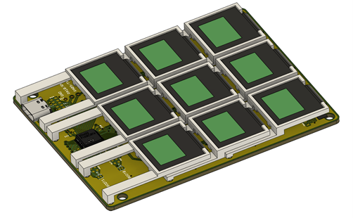
With all parts select I created a compact PCB that would hold nine OLEDs. The board contains mounting point for the 3D-printed button mechanism. On the “chin” of the device, where the levers of the last row of screen sit, there is just enough room for a USB-C connector and the STM32F1.Ultimately the wiring of this PCB is very simple. The STM32 is supplied by the USB connection and a 3.3V regulator. The regulator (AP2112K) also powers the nine LEDs, which contain internal dc-dc converters to create their working voltage of around 9V. USB-C is used for the connector, but it is wired as regular USB2.0. As the OLEDs can only assume one of two I²C addresses I had to use SPI. That means they share all data lines but they each have their own chip select.

Assembling the board can be tricky as the OLEDs have to be soldered in first before the 3D-printed mounts are put in place. There is only enough room to get them in place in a certain order without damaging the display connectors. I did not want to leave the PCB and mechanisms exposed so designed and printed a simple case. The PCB snaps into it and the buttons get covered with a face plate. I originally planned to put transparent acrylic on the OLED panels, but it looks much nicer without them. As the screens are made from glass, scratches should not be a big issue.

The STM32 can be programmed via USB after initially flashing the USB bootloader (stm32duino bootloader). Currently there are two different Arduino implementations for the STM32 boards. An official one by ST and the Arduino_STM32 port by Roger Melbourne. The latter contains more features, including some that are needed for this project. To make the keyboard work as a HID (human interface device) I used the STM32F1 USB composite library. With this library the STM32 cannot just mimic a HID device, but a serial port simultaneously. This enables the keyboard to be controlled over a COM port while still being an independent HID keyboard. The firmware I created is very simple as the Adafruit GFX library includes most the code needed to drive the displays. What turned out to be much more complicated was the desktop app that would be used to control the keyboard.
-
Hardware
Max.K • 12/09/2020 at 20:26 • 0 commentsThe first task was to figure out how to build a button with an integrated display. There actually are off-the-shelf solutions: NKK switches manufacture tactile switches with color displays. But at a crazy 50€ or more per key these are out of the question. Early on I decided to use small OLED displays as they are widely available and inexpensive at under 3€.
I found that 0.66in OLEDs are just the right size to allow for a compact keyboard. And their 64x48 pixels provide enough resolution to display useful icons. The displays consist of a glass panel with a flex connector that can be soldered directly to the PCB. When bending the connector under the display glass, a gap of a few mm is formed, just enough to fit a thin tactile switch in it. What’s left is a mechanism that supports the display so that when the OLED is pushed, the tactile switch is pressed.
Figuring out the key mechanism turned out to be challenging. The display has a big surface area compared to the tiny tactile switch. When pressing the button, the force needs to be evenly distributed. If not, pressing on the edge of the OLED will just rotate it around the button. I learned this when I 3D-printed my first OLED mount. It simply holds the display in place but does not limit its rotation: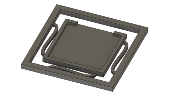
Laptop keyboards solve this by using a scissor mechanism that restricts the key to a linear motion. However, I could not think of an easy way to 3D-print this mechanism without making it unnecessarily big. The solution for me was to add a cantilever to the display mount. This lets the display rotate around the point where the levers are connected to the PCB and the motion is sufficiently linear for the tactile switch to be pressed.
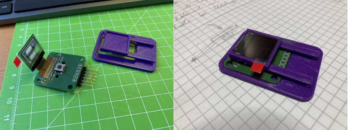
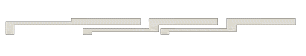
I continued to create a single button keyboard as a proof of concept. After a few iterations the mechanism was working. Whatever point on the screen was pushed, the button was actuated with a satisfying tactile click. The cantilever mechanism is very compact as it does not add to the height of the OLED itself. It also can be stacked to allow for a tight placement of multiple buttons in a keyboard. For this, the lever of one key overlaps with the screen of the next.
With the basics of the macro keyboard working, I went on to select the remaining electronic components.
Recommend
About Joyk
Aggregate valuable and interesting links.
Joyk means Joy of geeK