

Tracking Satellites: The Nitty Gritty Details
source link: https://hackaday.com/2020/12/16/tracking-satellites-the-nitty-gritty-details/
Go to the source link to view the article. You can view the picture content, updated content and better typesetting reading experience. If the link is broken, please click the button below to view the snapshot at that time.

If you want to listen to satellites, you have to be able to track them as they pass over the sky. When I first started tracking amateur satellites, computing the satellite’s location in the sky was a part of the challenge. Nowadays, that’s trivial. What’s left over are all the extremely important real-world details. Let’s take a look at a typical ham satellite tracking setup and see how it all ties together.
Rotators for Steering
The popularity of robotics, 3D printing, and CNC machines has resulted in a deluge of affordable electric motors and drivers. It’s hard to imagine that an electric motor for rotating an antenna would be anything special, but in fact, antenna rotators are non-trivial engineering designs. Most of the challenges are mechanical, not electrical — the antennas that they drive can be huge, have significant wind loading and rotational inertial, and just downright weigh a lot. A rotator design has to consider bearings, weather exposure, all kinds of loads, not just rotational. And usually a brake is required to keep the antenna pointed in windy conditions.
There’s been a 70-some year history of these mechanisms from back in the 1950s when Cornell Dubilier Electronics, the company you know as a capcacitor manufacturer, began making these rotators for television antennas in the 1950s. I was a little surprised to see that the rotator systems you can buy today are not very different from the ones we used in the 1980s, other than improved electronic controls.
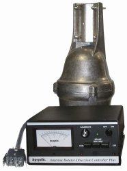 Typical Azimuth Rotator
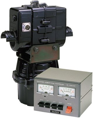
These rotator systems tend to be quite beefy, as HF antennas can be large. Fortunately in the case of amateur satellite communications only small Yagi antennas are needed. This simplifies the design if only because the equivalent surface area and weight of the antennas are much less. Commercial manufacturers have developed two-axis rotator combinations, such as this Yaesu model below, which is more compact and easier to setup. But some people might argue that this takes the fun out of the installation.
For those people, the smaller size and less stringent requirements means that homebrew rotators are well within reach and suitable to this environment. Furthermore, some satellite tracking stations these days are portable and can be installed on a camera tripod in an hour’s time, the weatherproofing requirement all but goes away. Heavy winds that might damage the bearings aren’t much of concern if the whole tripod topples over before the damage can be done.
One final advantage for doing it yourself is that pressing a normal rotator into service on the elevation axis might be tricky. Conventional rotators are designed to operate vertically. Turning one sideways might not work. Here’s where spinning your own design might be easier than adapting an existing rotator. Browse the Internet for satellite tracking designs, or just design your own. Use a tripod, don’t worry about the weather and wind, and enjoy the satisfaction of seeing your firmware moving those antenna across the sky.
One Loop Can Be Ignored
Rotating the antennas to a commanded location represents one control loop. But there is another control loop that has been traditionally ignored: is your RF beam truly pointed at the satellite? Getting feedback to close this loop is a much more difficult problem, and fortunately an unnecessary one in ham satellite communications. But for the curious, there are a couple of ways this has been solved in the past, both requiring a steady signal from the satellite to use as a beacon.
One technique is to continually “wobble” your antennas in a circle around the expected pointing angle. Let the diameter of the wobble circle be the 3 dB beamwidth of your antenna. Now dedicate a separate receiver to listen to the beacon signal (don’t forget it has to track doppler, too), and observe the signal strength versus the wobble, you can get the tracking error. If you are perfectly on-track, the signal strength will not vary with the wobble. But if you are off-track, then the signal will be vary, and the pointing error can be caclucated from this variation. This adds quite some complexity to the design, mechanically and electrically. Given the large beamwidths of antennas used for ham satellite operations, that wobble would be a crazy sight to behold. This kind of tracking is much better suited to smaller beamwidth antennas that are lighter in mass, and therefore easier to wobble.
Or better yet, wobble virtually. Without going in to the gory details, you can calculate the off-axis angles by using multiple antennas in a phased array receiver. But if you want to apply this technique, you would need at least four antennas instead of one.
Why would the calculated position be wrong? Truth is, it’s rarely wrong. Satellite orbits are well established and their parameters are updated frequently. In fact, they are often integral components of calibration procedures themselves. If your station clock is accurate and its location is accurately known, the only real errors are going to be with the antenna system: error in the feedback, error in the orientation of the antenna mast, and mis-alignment of the RF beam vs. the mechanical axis of the antenna. Fortunately, the broad beamwidths of the typical ham satellite antennas mean that success can be had without needing to take extraordinary measures.
Antennas: Crossed Yagis and Polarization
You often see Yagi antennas for satellite communications arranged in an “X” pattern, called “crossed Yagis”. The reason is to accomodate different signal polarizations, either during a pass as conditions change, or for satellite to satellite variations. The best case is when the transmitted signal has the exact same polarization as the receiving antenna when it arrives. The worse case is if the two polarizations are orthogonal — say, you have a horizontally polarized antenna receiving signals from a vertically polarized one. In theory, you won’t hear anything — a complete mismatch. This is the same concept as polarized light filters we’re all familiar with.
I used the term arriving polarization, because the signal can be modified as it passes through the atmosphere. The satellite antenna itself might be moving, too, as it passes overhead. There are several tricks to deal with this. One is to use a single antenna positioned at a 45 degree angle. Then we will always receive H and V polarized signals, but both will come with a 3 dB loss. Another method is to physically rotate the Yagi polarization as needed to match the incoming signal. This can be done manually or by motors: conceptually yet another “axis” of rotation to consider.
But the more common approach is to use two Yagis mounted on a common boom. You can just switch between H and V to get the best signal, using a RF relay. Or, you can obtain circular polarization by adding a phase delay line and a combiner, and a relay will let you switch between clockwise or counterclockwise rotation. The math here is really crazy, but the bottom line is that any linear polarization will couple to a circularly polarized antenna with a 3 dB loss, no matter its angle.
Auxilliary Equipment
Because of cable loss at VHF and UHF frequencies, you typically need to locate additional equipment, such as a power amplifier, receiver pre-amps, RF relays and power supplies, at the antenna and not in the shack. These things need power, control, and status feedback, and will inevitably add complexity to the satellite station controller. Except for maybe getting mains power safely to the roof, these issues are much simpler to solve today than back in the 1980s.
Making Everything Play Together, 35 Years On
Controlling traditional rotators hasn’t really changed much. You basically mimic a human pressing the buttons by wiring a relay in parallel with the switches. If you have a modern controller, it might be even easier. The Yaesu rotator mentioned above has an RS-232 interface to control both azimuth and elevation. It even has an internal table of positions vs time, which you can pre-load with a satellite pass and let the smart rotator drive the antennas. But this takes away all the fun of building a tracker yourself.
I see no reason to make an open-loop system anymore, at least from a cost perspective. There are many approachable ways to close the pointing loop today. One technique would be to use a MEMS chip, such as TDK’s MotionTracking or ST Microelectronics iNEMO family of chips that Ted Yapo wrote about last year. Another idea would be to use a monitoring camera and computer vision algorithms to calculate the pointing angle (although you might need to put some strategically placed LEDs on your antennas for night operations). Or you could do it the usual way, incorporating a position sensor in each axis. Usually the feedback signal would be sent by wires, which have to jump across a rotating joint. While such feedback could be sent wirelessly, adding a few more wires isn’t really a problem — you already need cables to power and control the rotators, and of course RF coaxial cables to connect to the antennas.
Kepler’s laws of orbital mechanics haven’t changed. Whether you write your own algorithms, borrow some from an open source repository, or purchase a commercial software package, there are plenty of software choices to match your budget or skill level. But the options for user interface have changed drastically, and for the better.
While talking with some C64 folks online about my tracker restoration project, I realized just how dumb my old tracker program UI was. But today, using various libraries and data sets, your program could easily draw satellite data visually in real time. I was even able to draw a satellite orbit in OpenSCAD in short order.
One huge advancement is the ease of getting satellite tracking data from NASA. No more paper tables in the mail or modem links to BBS systems — you can get satellite parameters with a few clicks of the mouse and an internet connection.
If you are interested in Ham radio satellites and antenna tracking, there’s never been a better time to get involved. The price of entry, monetarily- and technologically-speaking, has never been better.
Recommend
About Joyk
Aggregate valuable and interesting links.
Joyk means Joy of geeK